Infiniti EX35. Manual — part 72
AV
COMMUNICATION SIGNAL CIRCUIT (CONT-SAT)
AV-69
< COMPONENT DIAGNOSIS >
[BASE AUDIO WITHOUT NAVIGATION]
C
D
E
F
G
H
I
J
K
L
M
B
A
O
P
COMMUNICATION SIGNAL CIRCUIT (CONT-SAT)
Description
INFOID:0000000003508414
Satellite radio tuner and AV control unit are connected with a serial communication. They transmit the opera-
tion signal from AV control unit to satellite radio tuner, and transmit the display signal from satellite radio tuner
to AV control unit.
Diagnosis Procedure
INFOID:0000000003508415
1.
CHECK CONTINUITY COMMUNICATION SIGNAL CIRCUIT
1.
Turn ignition switch OFF.
2.
Disconnect satellite radio tuner connector and AV control unit connector.
3.
Check continuity between satellite radio tuner harness connector and AV control unit harness connector.
4.
Check continuity between satellite radio tuner harness connector and ground.
Is the inspection result normal?
YES
>> GO TO 2.
NO
>> Repair harness or connector.
2.
CHECK COMMUNICATION SIGNAL (SAT
→
CONT)
1.
Connect satellite radio tuner connector and AV control unit connector.
2.
Turn ignition switch ON.
3.
Check signal between satellite radio tuner harness connector and ground.
Is the inspection result normal?
YES
>> GO TO 3.
NO
>> Replace satellite radio tuner.
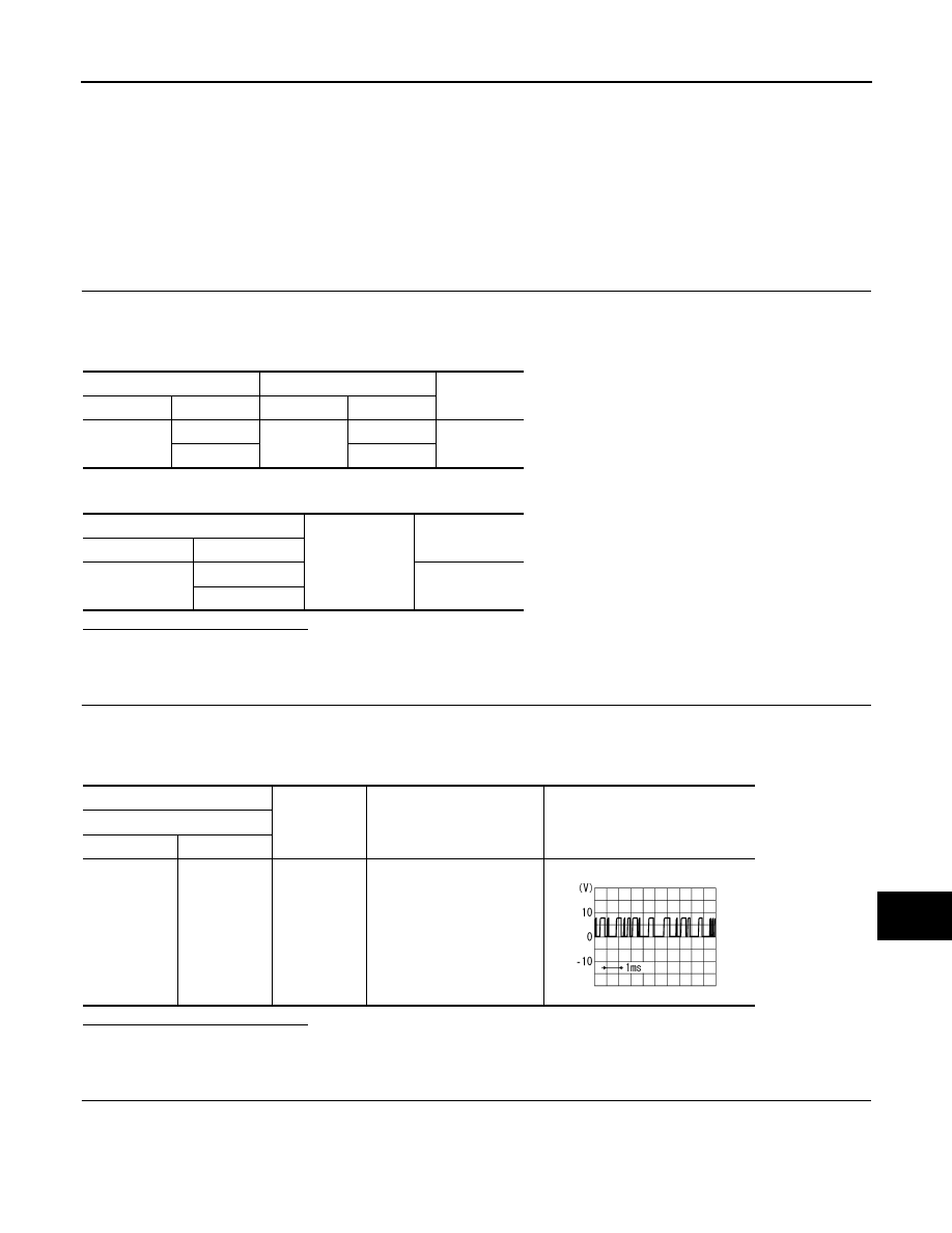
3.
CHECK COMMUNICATION SIGNAL (CONT
→
SAT)
Check signal between satellite radio tuner harness connector and ground.
Satellite radio tuner
AV control unit
Continuity
Connector
Terminals
Connector
Terminals
B236
9
M82
29
Existed
10
30
Satellite radio tuner
Ground
Continuity
Connector
Terminals
B236
9
Not existed
10
(+)
(
−
)
Condition
Reference value
Satellite radio tuner
Connector
Terminal
B236
9
Ground
When satellite radio mode is
selected.
SKIA9300J
AV-70
< COMPONENT DIAGNOSIS >
[BASE AUDIO WITHOUT NAVIGATION]
COMMUNICATION SIGNAL CIRCUIT (CONT-SAT)
Is the inspection result normal?
YES
>> Replace satellite radio tuner.
NO
>> Replace AV control unit.
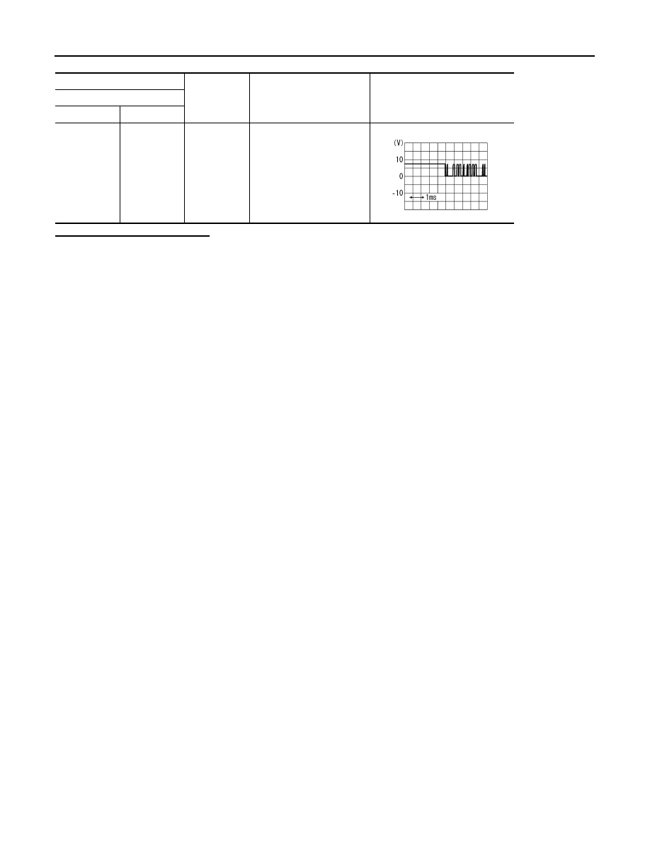
(+)
(
−
)
Condition
Reference value
Satellite radio tuner
Connector
Terminal
B236
10
Ground
When satellite radio mode is
selected.
SKIA9301J
AV
REQUEST SIGNAL CIRCUIT (SAT
→
CONT)
AV-71
< COMPONENT DIAGNOSIS >
[BASE AUDIO WITHOUT NAVIGATION]
C
D
E
F
G
H
I
J
K
L
M
B
A
O
P
REQUEST SIGNAL CIRCUIT (SAT
→
CONT)
Description
INFOID:0000000003508416
Request signal transmits the signal to recognize the connection of satellite radio tuner from satellite radio
tuner to AV control unit.
Diagnosis Procedure
INFOID:0000000003508417
1.
CHECK CONTINUITY REQUEST SIGNAL CIRCUIT
1.
Turn ignition switch OFF.
2.
Disconnect satellite radio tuner connector and AV control unit connector.
3.
Check continuity between satellite radio tuner unit harness connector and AV control unit harness connec-
tor.
4.
Check continuity between satellite radio tuner harness connector and ground.
Is the inspection result normal?
YES
>> GO TO 2.
NO
>> Repair harness or connector.
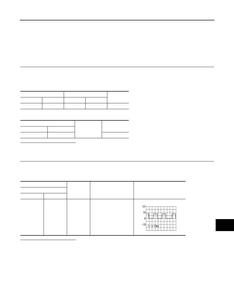
2.
CHECK COMMUNICATION SIGNAL
1.
Connect satellite radio tuner connector and AV control unit connector.
2.
Turn ignition switch ON.
3.
Check signal between satellite radio tuner harness connector and ground.
Is the inspection result normal?
YES
>> Replace AV control unit.
NO
>> Replace satellite radio tuner.
Satellite radio tuner
AV control unit
Continuity
Connector
Terminal
Connector
Terminal
B236
8
M82
28
Existed
Satellite radio tuner
Ground
Continuity
Connector
Terminal
B236
8
Not existed
(+)
(
−
)
Condition
Reference value
Satellite radio tuner
Connector
Terminal
B236
8
Ground
When satellite radio mode is
selected.
SKIA9299J
AV-72
< COMPONENT DIAGNOSIS >
[BASE AUDIO WITHOUT NAVIGATION]
STEERING ANGLE SENSOR SIGNAL CIRCUIT
STEERING ANGLE SENSOR SIGNAL CIRCUIT
Description
INFOID:0000000003529087
• Steering angle sensor signal 1, 2 detects the turning direction and quantity of the steering and transmits it to
the camera control unit.
• Steering angle sensor signal 3 detects the neutral position of the steering and transmits it to the camera con-
trol unit.
• Camera control unit performs the correction of neutral position with sensor signal 1, 2, 3 and vehicle speed
signal.
Diagnosis Procedure
INFOID:0000000003529088
1.
CHECK CONTINUITY STEERING ANGLE SENSOR SIGNAL CIRCUIT
1.
Turn ignition switch OFF.
2.
Disconnect camera control unit connector and steering angle sensor connector.
3.
Check continuity between camera control unit harness connector and steering angle sensor harness con-
nector.
4.
Check continuity between camera control unit harness connector and ground.
Is inspection result normal?
YES
>> GO TO 2.
NO
>> Repair harness or connector.
2.
CHECK VOLTAGE CAMERA CONTROL UNIT
1.
Connect camera control unit connector.
2.
Turn ignition switch ON.
3.
Check voltage between camera control unit harness connector and ground.
Is inspection result normal?
YES
>> GO TO 3.
NO
>> Replace camera control unit.
3.
CHECK STEERING ANGLE SENSOR SIGNAL
1.
Turn ignition switch OFF.
2.
Connect steering angle sensor connector.
Camera control unit
Steering angle sensor
Continuity
Connector
Terminals
Connector
Terminals
B50
23
M37
3
Existed
24
4
25
5
Camera control unit
Ground
Continuity
Connector
Terminals
B50
23
Not existed
24
25
(+)
(
−
)
Reference value
(Approx.)
Camera control unit
Connector
Terminals
B50
23
Ground
5.0 V
24
25
Нет комментариевНе стесняйтесь поделиться с нами вашим ценным мнением.
Текст