Infiniti EX35. Manual — part 71
AV
REAR VIEW CAMERA IMAGE SIGNAL CIRCUIT
AV-65
< COMPONENT DIAGNOSIS >
[BASE AUDIO WITHOUT NAVIGATION]
C
D
E
F
G
H
I
J
K
L
M
B
A
O
P
REAR VIEW CAMERA IMAGE SIGNAL CIRCUIT
Description
INFOID:0000000003529077
• Camera control unit outputs camera ON signal to rear view camera and inputs rear view camera image sig-
nal from rear view camera when the reverse signal is input.
• The camera control unit that inputs the camera image signal transmits the camera image signal to the AV
control unit.
Diagnosis Procedure
INFOID:0000000003529078
1.
CHECK CONTINUITY CAMERA IMAGE SIGNAL CIRCUIT
1.
Turn ignition switch OFF.
2.
Disconnect camera control unit connector and rear view camera connector.
3.
Check continuity between camera control unit harness connector and rear view camera harness connec-
tor.
4.
Check continuity between camera control unit harness connector and ground.
Is inspection result normal?
YES
>> GO TO 2.
NO
>> Repair harness or connector.
2.
CHECK CAMERA IMAGE SIGNAL
1.
Connect camera control unit connector and rear view camera connector.
2.
Turn ignition switch ON.
3.
Check signal between camera control unit harness connector and ground.
Is inspection result normal?
YES
>> Replace camera control unit.
NO
>> Replace rear view camera.
Camera control unit
Rear view camera
Continuity
Connector
Terminal
Connector
Terminal
B50
6
D121
3
Existed
Camera control unit
Ground
Continuity
Connector
Terminal
B50
6
Not existed
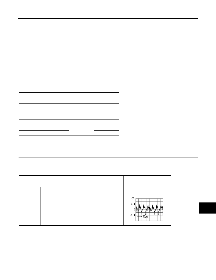
(+)
(
−
)
Condition
Reference value
Camera control unit
Connector
Terminal
B50
6
Ground
At rear view camera image
is displayed.
SKIB2251J
AV-66
< COMPONENT DIAGNOSIS >
[BASE AUDIO WITHOUT NAVIGATION]
REAR VIEW CAMERA POWER SUPPLY
REAR VIEW CAMERA POWER SUPPLY
Description
INFOID:0000000003529081
• Camera control unit outputs camera ON signal to rear view camera and inputs rear view camera image sig-
nal from rear view camera when the reverse signal is input.
• The camera control unit that inputs the camera image signal transmits the camera image signal to the AV
control unit.
Diagnosis Procedure
INFOID:0000000003529082
1.
CHECK CONTINUITY CAMERA ON SIGNAL CIRCUIT
1.
Turn ignition switch OFF.
2.
Disconnect camera control unit connector and rear view camera connector.
3.
Check continuity between camera control unit harness connector and rear view camera harness connec-
tor.
4.
Check continuity between camera control unit harness connector and ground.
Is inspection result normal?
YES
>> GO TO 2.
NO
>> Repair harness or connector.
2.
CHECK VOLTAGE CAMERA ON SIGNAL
1.
Connect camera control unit connector and rear view camera connector.
2.
Turn ignition switch ON.
3.
Check signal between camera control unit harness connector and ground.
Is inspection result normal?
YES
>> Replace rear view camera.
NO
>> Replace camera control unit.
Camera control unit
Rear view camera
Continuity
Connector
Terminal
Connector
Terminal
B50
8
D121
1
Existed
Camera control unit
Ground
Continuity
Connector
Terminal
B50
8
Not existed
(+)
(
−
)
Condition
Reference
value
(Approx.)
Camera control unit
Connector
Terminal
B50
8
Ground
Shift position
is “R”
6.0 V
AV
CAMERA IMAGE SIGNAL CIRCUIT (CAMERA CONTROL UNIT TO AV CON-
TROL UNIT)
AV-67
< COMPONENT DIAGNOSIS >
[BASE AUDIO WITHOUT NAVIGATION]
C
D
E
F
G
H
I
J
K
L
M
B
A
O
P
CAMERA IMAGE SIGNAL CIRCUIT (CAMERA CONTROL UNIT TO AV
CONTROL UNIT)
Description
INFOID:0000000003529083
• Camera control unit outputs camera ON signal to rear view camera and inputs rear view camera image sig-
nal from rear view camera when the reverse signal is input.
• The camera control unit that inputs the camera image signal transmits the camera image signal to the AV
control unit.
Diagnosis Procedure
INFOID:0000000003529084
1.
CHECK CONTINUITY CAMERA IMAGE SIGNAL CIRCUIT (CAMERA CONTROL UNIT TO AV CONTROL
UNIT)
1.
Turn ignition switch OFF.
2.
Disconnect camera control unit connector and AV control unit connector.
3.
Check continuity between camera control unit harness connector and AV control unit harness connector.
4.
Check continuity between camera control unit harness connector and ground.
Is inspection result normal?
YES
>> GO TO 2.
NO
>> Repair harness or connector.
2.
CHECK CAMERA IMAGE SIGNAL (CAMERA CONTROL UNIT TO AV CONTROL UNIT)
1.
Connect camera control unit connector and AV control unit connector.
2.
Turn ignition switch ON.
3.
Check signal between camera control unit harness connector and ground.
Is inspection result normal?
YES
>> Replace AV control unit.
NO
>> Replace camera control unit.
Camera control unit
AV control unit
Continuity
Connector
Terminal
Connector
Terminal
B50
12
M84
65
Existed
Camera control unit
Ground
Continuity
Connector
Terminal
B50
12
Not existed
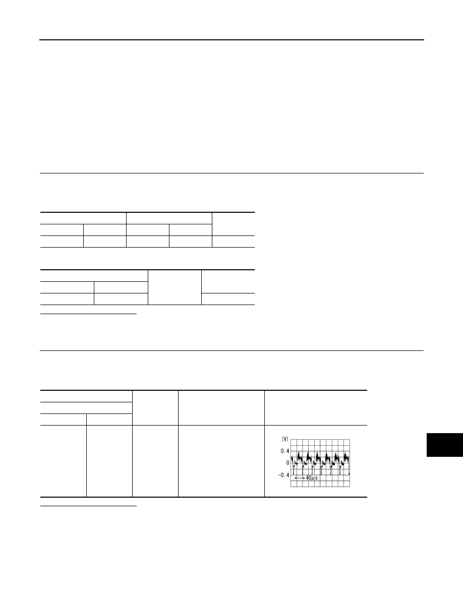
(+)
(
−
)
Condition
Reference value
Camera control unit
Connector
Terminal
B50
12
Ground
At rear view camera image
is displayed.
SKIB2251J
AV-68
< COMPONENT DIAGNOSIS >
[BASE AUDIO WITHOUT NAVIGATION]
COMPOSITE IMAGE SIGNAL CIRCUIT
COMPOSITE IMAGE SIGNAL CIRCUIT
Description
INFOID:0000000003529085
AV control unit that inputs the camera image signal and AUX image signal transmits the composite image sig-
nal to the display unit.
Diagnosis Procedure
INFOID:0000000003529086
1.
CHECK CONTINUITY COMPOSITE IMAGE SIGNAL CIRCUIT (AV CONTROL UNIT TO DISPLAY UNIT)
1.
Turn ignition switch OFF.
2.
Disconnect AV control unit connector and display unit connector.
3.
Check continuity between AV control unit harness connector and display unit harness connector.
4.
Check continuity between AV control unit harness connector and ground.
Is inspection result normal?
YES
>> GO TO 2.
NO
>> Repair harness or connector.
2.
CHECK COMPOSITE IMAGE SIGNAL (AV CONTROL UNIT TO DISPLAY UNIT)
1.
Connect AV control unit connector and display unit connector.
2.
Turn ignition switch ON.
3.
Check signal between AV control unit harness connector and ground.
Is inspection result normal?
YES
>> Replace display unit.
NO
>> Replace AV control unit.
AV control unit
Display unit
Continuity
Connector
Terminal
Connector
Terminal
M83
36
M71
15
Existed
AV control unit
Ground
Continuity
Connector
Terminal
M83
36
Not existed
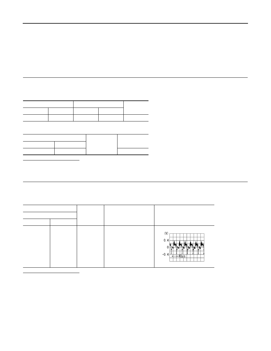
(+)
(
−
)
Condition
Reference value
AV control unit
Connector
Terminal
M83
36
Ground
At rear view camera or AUX
image is displayed.
SKIB2251J
Нет комментариевНе стесняйтесь поделиться с нами вашим ценным мнением.
Текст