Infiniti EX35. Manual — part 1216
RAX-4
< PREPARATION >
PREPARATION
PREPARATION
PREPARATION
Special Service Tool
INFOID:0000000003138877
The actual shapes of Kent-Moore tools may differ from those of special service tools illustrated here.
Commercial Service Tool
INFOID:0000000003138878
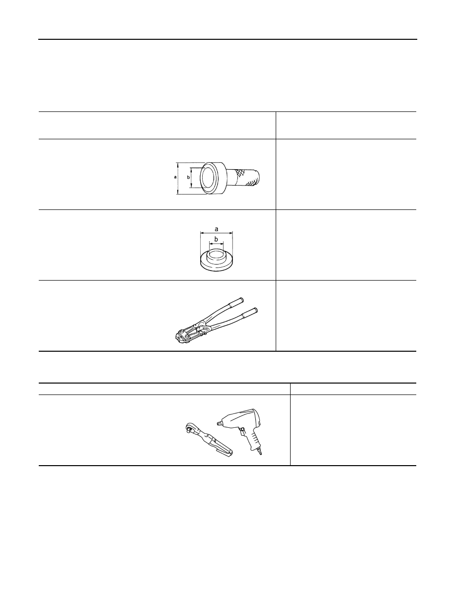
Tool number
(Kent-Moore No.)
Tool name
Description
KV38100500
(
−
)
Drift
a: 80 mm (3.15 in) dia.
b: 60 mm (2.36 in) dia.
Installing drive shaft plug
KV38102200
(
−
)
Drift
a: 90 mm (3.54 in) dia.
b: 31 mm (1.22 in) dia.
Installing drive shaft plug
KV40107300
(
−
)
Boot band crimping tool
Installing boot band
ZZA0701D
ZZA0920D
ZZA1229D
Tool name
Description
Power tool
Loosening bolts and nuts
PBIC0190E
REAR WHEEL HUB AND HOUSING
RAX-5
< ON-VEHICLE MAINTENANCE >
C
E
F
G
H
I
J
K
L
M
A
B
RAX
N
O
P
ON-VEHICLE MAINTENANCE
REAR WHEEL HUB AND HOUSING
Inspection
INFOID:0000000003138879
MOUNTING INSPECTION
Make sure the mounting conditions (looseness, back lash) of each component and component conditions
(wear, damage) are normal.
WHEEL BEARING INSPECTION
• Move wheel hub and bearing assembly in the axial direction by hand. Make sure there is no looseness of
wheel bearing.
• Rotate wheel hub, and make sure that is no unusual noise or other irregular conditions. If there is any of
irregular conditions, replace wheel hub and bearing assembly.
Standard
Axial end play
: Refer to
RAX-6
< ON-VEHICLE MAINTENANCE >
REAR DRIVE SHAFT
REAR DRIVE SHAFT
Inspection
INFOID:0000000003138880
• Check drive shaft mounting point and joint for looseness and other damage.
• Check boot for cracks and other damage.
CAUTION:
Replace entire drive shaft assembly when noise or vibration occur from drive shaft.
REAR WHEEL HUB AND HOUSING
RAX-7
< ON-VEHICLE REPAIR >
C
E
F
G
H
I
J
K
L
M
A
B
RAX
N
O
P
ON-VEHICLE REPAIR
REAR WHEEL HUB AND HOUSING
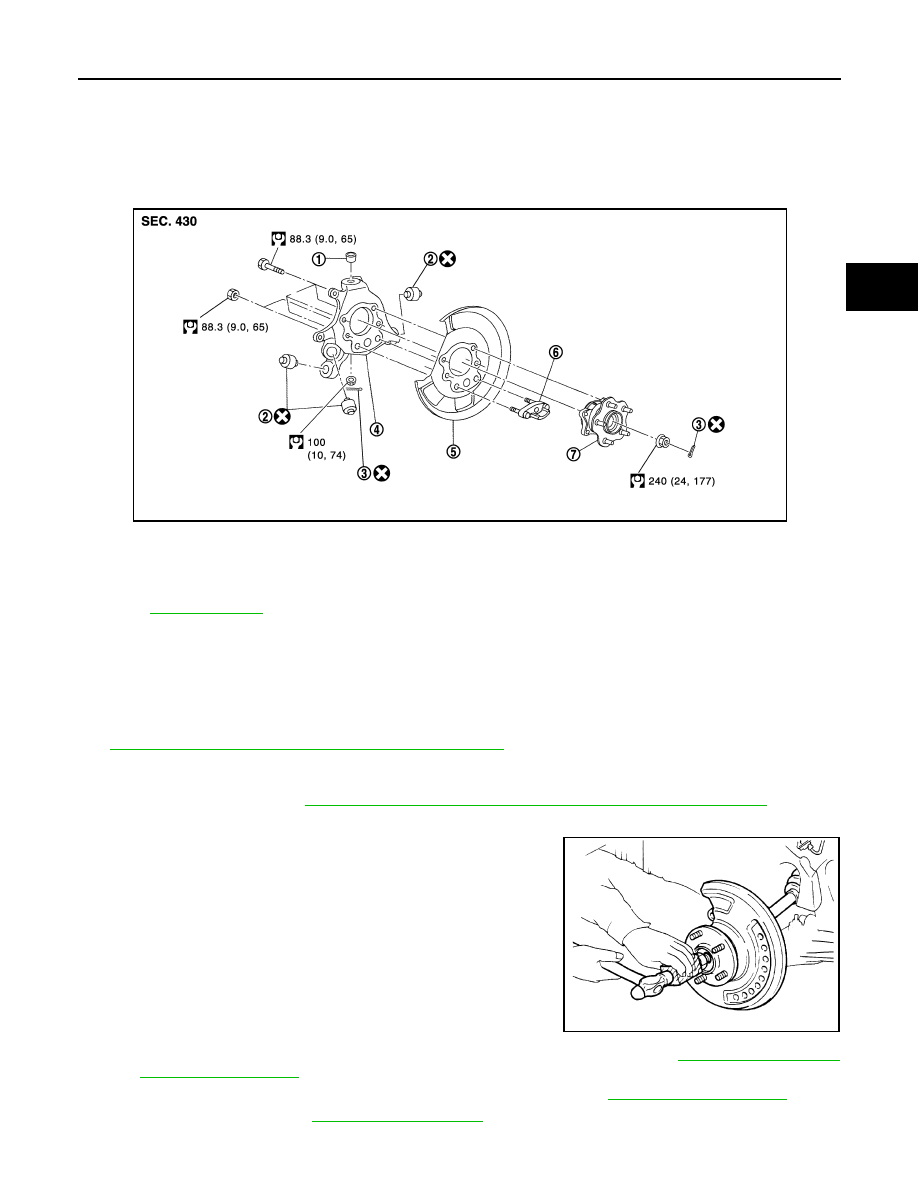
Exploded View
INFOID:0000000003138881
Removal and Installation
INFOID:0000000003138882
REMOVAL
1.
Remove tire with power tool.
2.
Remove caliper assembly with power tool. Hang it in a place where it will not interfere with work. Refer to
BR-40, "BRAKE CALIPER ASSEMBLY : Exploded View"
CAUTION:
Never depress brake pedal while caliper assembly is removed.
3.
Remove disc rotor. Refer to
BR-41, "BRAKE CALIPER ASSEMBLY : Removal and Installation"
.
4.
Remove cotter pin, then loosen hub lock nut with a power tool.
5.
Patch hub lock nut with a piece of wood. Hammer the wood to
disengage wheel hub and bearing assembly from drive shaft.
Take out the hub lock nut.
CAUTION:
• Never place drive shaft joint at an extreme angle. Also be
careful not to overextend slide joint.
• Never allow drive shaft to hang down without support for
counterpart such as joint sub-assembly, and other parts.
NOTE:
Use a suitable puller, if wheel hub and bearing assembly and
drive shaft cannot be separated even after performing the above
procedure.
6.
Remove parking brake shoe and parking brake cable from back plate. Refer to
7.
Remove stabilizer connecting rod (upper side) with power tool. Refer to
.
8.
Remove coil spring. Refer to
9.
Set suitable jack under axle housing.
1.
Ball seat
2.
Bushing
3.
Cotter pin
4.
Axle housing
5.
Back plate
6.
Anchor block
7.
Wheel hub and bearing assembly
Refer to
JPDIG0100GB
JPDIG0070ZZ
Нет комментариевНе стесняйтесь поделиться с нами вашим ценным мнением.
Текст