Infiniti EX35. Manual — part 857

TRANSVERSE LINK
FSU-13
< ON-VEHICLE REPAIR >
[2WD]
C
D
F
G
H
I
J
K
L
M
A
B
FSU
N
O
P
TRANSVERSE LINK
Exploded View
INFOID:0000000003129907
Removal and Installation
INFOID:0000000003129908
REMOVAL
1.
Remove tires with power tool.
2.
Remove under cover with power tool.
3.
Remove strut. Refer to
.
4.
Remove steering outer socket from steering knuckle. Refer to
.
5.
Remove transverse link from steering knuckle.
6.
Set suitable jack under transverse link.
7.
Remove transverse link and insulator.
INSTALLATION
Note the following, and install in the reverse order of removal.
• Never tap on the ball joint cap of the stabilizer connecting rod with a hammer or a similar item when inserting
the stabilizer connecting rod into the transverse link.
• Perform final tightening of bolts and nuts at the front suspension member installation and strut lower side
(rubber bushing), under unladen conditions with tires on level ground.
Inspection
INFOID:0000000003129909
INSPECTION AFTER REMOVAL
Appearance
Check the following items, and replace the part if necessary.
• Transverse link and bushing for deformation, cracks or damage.
• Ball joint boot for cracks or other damage, and also for grease leakage.
Ball Joint Inspection
Manually move ball stud to confirm it moves smoothly with no binding.
Swing Torque Inspection
NOTE:
1.
Stopper rubber
2.
Upper link
3.
Insulator
4.
Transverse link
5.
Front suspension member
Refer to
JPEIA0083GB
FSU-14
< ON-VEHICLE REPAIR >
[2WD]
TRANSVERSE LINK
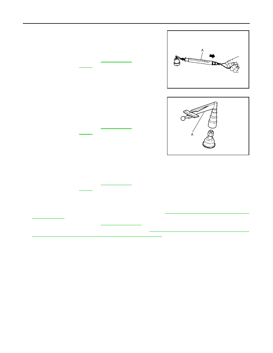
Before measurement, move ball stud at least ten times by hand to check for smooth movement.
• Hook a spring balance (A) at cotter pin mounting hole. Confirm
spring balance measurement value is within specifications when
ball stud begins moving.
- If swing torque exceeds standard range, replace transverse link
assembly.
Rotating Torque Inspection
• Attach mounting nut to ball stud. Make sure that rotating torque is
within specifications with a preload gauge (A) [SST: ST3127S000
(J-25765-A)].
- If rotating torque exceeds standard range, replace transverse link
assembly.
Axial End Play Inspection
• Move tip of ball stud in axial direction to check for looseness.
- If axial end play exceeds standard range, replace transverse link assembly.
INSPECTION AFTER INSTALLATION
1.
Check wheel sensor harness for proper connection. Refer to
BRC-107, "FRONT WHEEL SENSOR :
.
2.
Check wheel alignment. Refer to
.
3.
Adjust neutral position of steering angle sensor. Refer to
BRC-8, "ADJUSTMENT OF STEERING ANGLE
SENSOR NEUTRAL POSITION : Special Repair Requirement"
.
Standard
Swing toque
: Refer to
JPEIA0005ZZ
Standard
Rotating toque
: Refer to
PDIA1258E
Standard
Axial end play
: Refer to

UPPER LINK
FSU-15
< ON-VEHICLE REPAIR >
[2WD]
C
D
F
G
H
I
J
K
L
M
A
B
FSU
N
O
P
UPPER LINK
Exploded View
INFOID:0000000003129910
Removal and Installation
INFOID:0000000003129911
REMOVAL
1.
Remove tires with power tool.
2.
Remove strut. Refer to
.
3.
Remove upper link from steering knuckle with power tool. Refer to
4.
Remove upper link and stopper rubber.
INSTALLATION
Note the following, and install in the reverse order of removal.
• Perform final tightening of bolts and nuts at the vehicle installation position (rubber bushing), under unladen
conditions with tires on level ground.
Inspection
INFOID:0000000003129912
INSPECTION AFTER REMOVAL
Appearance
Check the following items, and replace the part if necessary.
• Upper link and bushing for deformation, cracks or damage.
• Ball joint boot for cracks or other damage, and also for grease leakage.
Ball Joint Inspection
Manually move ball stud to confirm it moves smoothly with no binding.
Swing Torque Inspection
NOTE:
Before measurement, move ball stud at least ten times by hand to check for smooth movement.
1.
Stopper rubber
2.
Upper link
3.
Insulator
4.
Transverse link
5.
Front suspension member
Refer to
JPEIA0083GB
FSU-16
< ON-VEHICLE REPAIR >
[2WD]
UPPER LINK
• Hook a spring balance (A) at cutout on ball stud. Confirm spring
balance measurement value is within specifications when ball stud
begins moving.
- If swing torque exceeds standard range, replace upper link assem-
bly.
Rotating Torque Inspection
• Attach mounting nut to ball stud. Make sure that rotating torque is
within specifications with a preload gauge (A) [SST: ST3127S000
(J-25765-A)].
- If rotating torque exceeds standard range, replace upper link
assembly.
Axial End Play Inspection
• Move tip of ball stud in axial direction to check for looseness.
- If axial end play exceeds standard range, replace upper link assembly.
INSPECTION AFTER INSTALLATION
1.
Check wheel sensor harness for proper connection. Refer to
BRC-107, "FRONT WHEEL SENSOR :
.
2.
Check wheel alignment. Refer to
.
3.
Adjust neutral position of steering angle sensor. Refer to
BRC-8, "ADJUSTMENT OF STEERING ANGLE
SENSOR NEUTRAL POSITION : Special Repair Requirement"
.
Standard
Swing torque
: Refer to
JPEIA0005ZZ
Standard
Rotarian torque
: Refer to
PDIA1258E
Standard
Axial end play
: Refer to
Нет комментариевНе стесняйтесь поделиться с нами вашим ценным мнением.
Текст