Infiniti EX35. Manual — part 858
FRONT STABILIZER
FSU-17
< ON-VEHICLE REPAIR >
[2WD]
C
D
F
G
H
I
J
K
L
M
A
B
FSU
N
O
P
FRONT STABILIZER
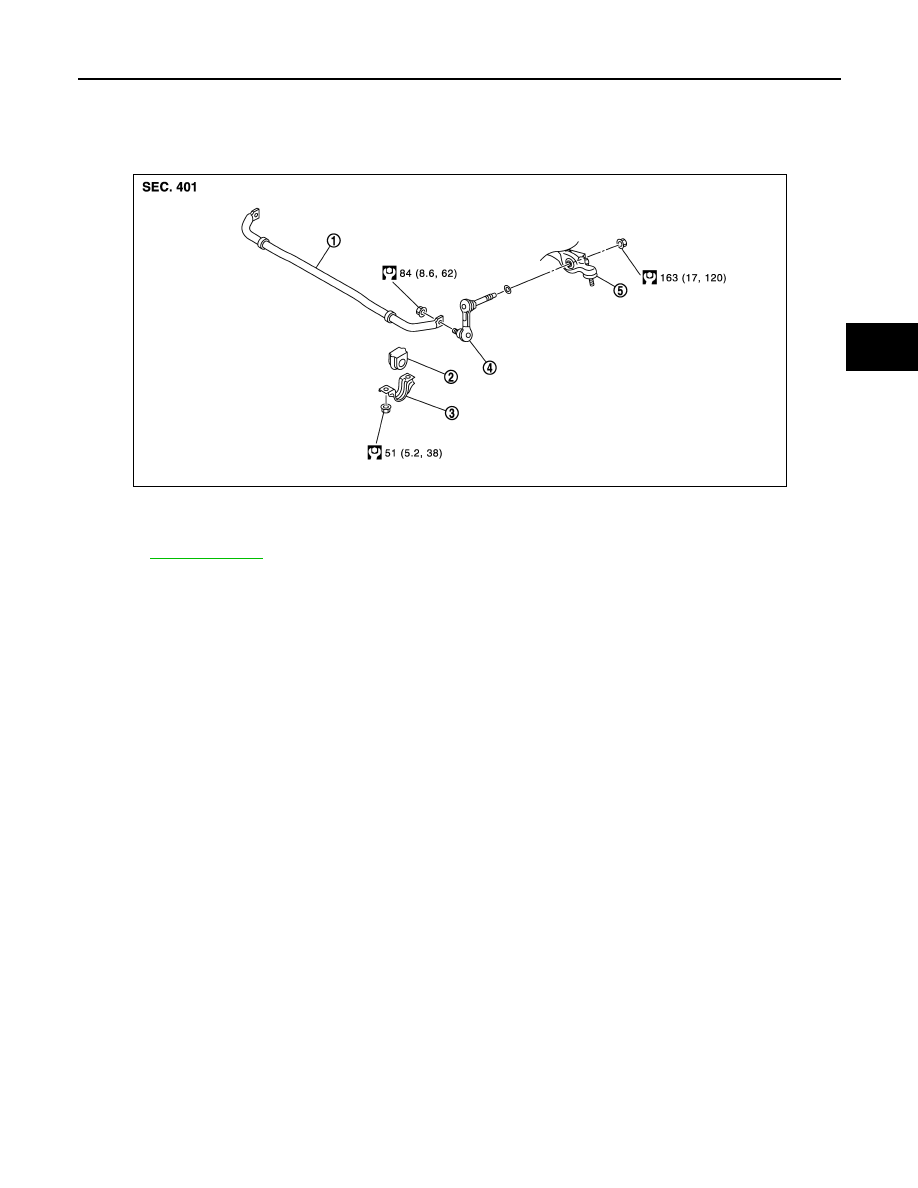
Exploded View
INFOID:0000000003129913
Removal and Installation
INFOID:0000000003129914
REMOVAL
1.
Remove tires with power tool.
2.
Remove under cover with power tool.
3.
Remove stabilizer connecting rod with power tool.
CAUTION:
Apply a matching mark to identify the installation position.
4.
Remove stabilizer clamp and stabilizer bushing.
5.
Remove stabilizer bar.
INSTALLATION
Note the following, and install in the reverse order of removal.
• Check the matching mark when installing.
• Tighten the mounting nut to the specified torque while holding a hexagonal part of stabilizer connecting rod
side.
Inspection
INFOID:0000000003129915
INSPECTION AFTER REMOVAL
Check stabilizer bar, stabilizer connecting rod, stabilizer bushing and stabilizer clamp for deformation, cracks
or damage. Replace it if necessary.
1.
Stabilizer bar
2.
Stabilizer bushing
3.
Stabilizer clamp
4.
Stabilizer connecting rod
5.
Transverse link
Refer to
JPEIA0084GB
FSU-18
< ON-VEHICLE REPAIR >
[2WD]
FRONT SUSPENSION MEMBER
FRONT SUSPENSION MEMBER
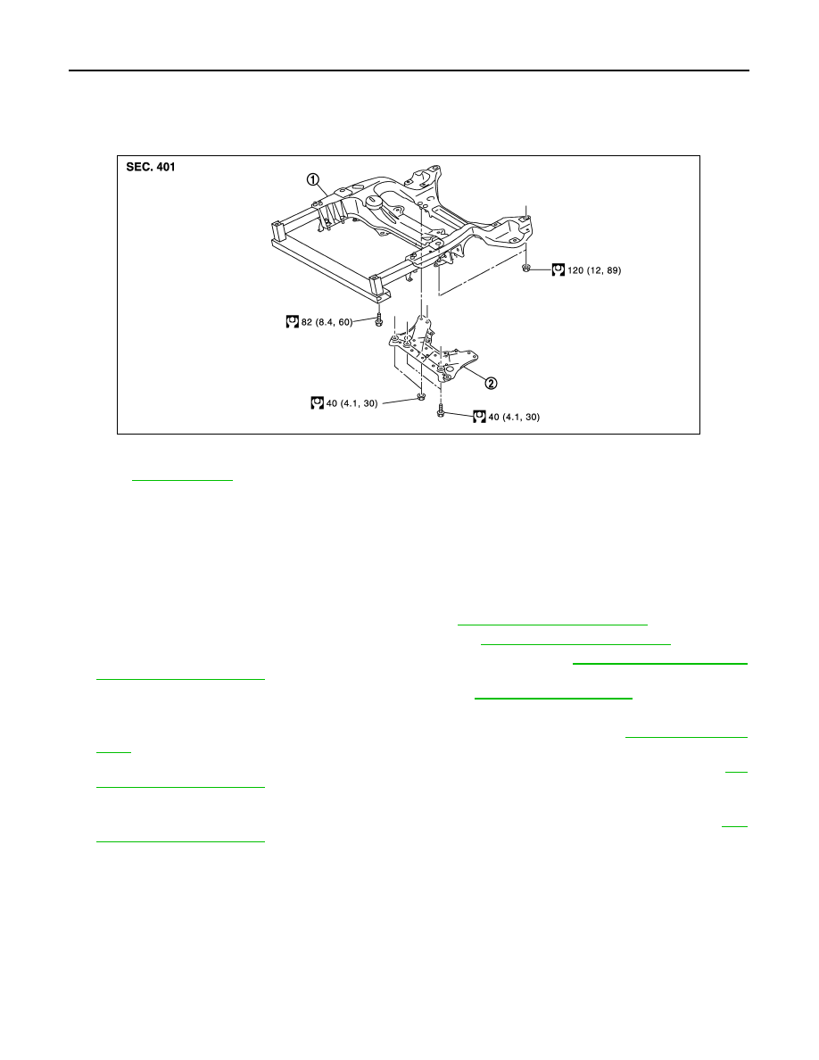
Exploded View
INFOID:0000000003129916
Removal and Installation
INFOID:0000000003129917
REMOVAL
1.
Remove tire with power tool.
2.
Remove under cover with power tool.
3.
Remove suspension member stay with power tool.
4.
Separate steering gear assembly and lower joint. Refer to
.
5.
Remove steering outer socket from steering knuckle. Refer to
.
6.
Remove wheel sensor and sensor harness from steering knuckle. Refer to
7.
Remove stabilizer connecting rod and stabilizer bar. Refer to
.
8.
Install engine slinger, and then hoist engine.
9.
Remove transverse link from front suspension member with power tool. Refer to
.
10. Remove steering hydraulic piping bracket and steering gear from front suspension member. Refer to
11. Set suitable jack front suspension member.
12. Remove mounting nuts between engine mounting insulator and from suspension member. Refer to
13. Remove mounting bolts and nuts of front suspension member with power tool.
14. Gradually lower jack to remove front suspension assembly from vehicle.
INSTALLATION
Note the following, and install in the reverse order of removal.
• Perform final tightening of bolts and nuts at the vehicle installation position (rubber bushing), under unladen
condition with tires on level ground.
Inspection
INFOID:0000000003129918
INSPECTION AFTER REMOVAL
1.
Front suspension member
2.
Suspension member stay
Refer to
for symbols in the figure.
JPEIA0085GB

FRONT SUSPENSION MEMBER
FSU-19
< ON-VEHICLE REPAIR >
[2WD]
C
D
F
G
H
I
J
K
L
M
A
B
FSU
N
O
P
Check the front suspension member for significant deformation, cracks, or damages. Replace if necessary.
INSPECTION AFTER INSTALLATION
1.
Check wheel sensor harness for proper connection. Refer to
BRC-107, "FRONT WHEEL SENSOR :
.
2.
Check wheel alignment. Refer to
3.
Adjust the neutral position of the steering angle sensor. Refer to
BRC-8, "ADJUSTMENT OF STEERING

FSU-20
< SERVICE DATA AND SPECIFICATIONS (SDS)
[2WD]
SERVICE DATA AND SPECIFICATIONS (SDS)
SERVICE DATA AND SPECIFICATIONS (SDS)
SERVICE DATA AND SPECIFICATIONS (SDS)
Wheel Alignment
INFOID:0000000003129922
Measure value under unladen* conditions.
*: Fuel, engine coolant and lubricant are full. Spare tire, jack, hand tools and mats are in designated positions.
Ball Joint
INFOID:0000000003129923
Item
Standard
Camber
Degree minute (Decimal degree)
Minimum
–0
°
40
′
(–0.66
°
)
Nominal
0
°
05
′
(0.08
°
)
Maximum
0
°
50
′
(0.83
°
)
Left and right difference
0
°
33
′
(0.55
°
) or less
Caster
Degree minute (Decimal degree)
Minimum
3
°
30
′
(3.50
°
)
Nominal
4
°
15
′
(4.25
°
)
Maximum
5
°
00
′
(5.00
°
)
Left and right difference
0
°
39
′
(0.65
°
) or less
Kingpin inclination
Degree minute (Decimal degree)
Minimum
6
°
05
′
(6.09
°
)
Nominal
6
°
50
′
(6.83
°
)
Maximum
7
°
35
′
(7.58
°
)
Total toe-in
Distance
Minimum
0 mm (0 in)
Nominal
In 1 mm (0.04 in)
Maximum
In 2 mm (0.08 in)
Angle (left wheel or right wheel)
Degree minute (Decimal Degree)
Minimum
0
°
00 (0.00
°
)
Nominal
In 0
°
02
′
24
″
(0.04
°
)
Maximum
In 0
°
04
′
48
″
(0.08
°
)
Item
Standard
Swing torque
Transverse link
0.5 – 3.6 N·m (0.06 – 0.36 kg-m, 5 – 31 in-lb)
Upper link
0 – 2.0 N·m (0 – 0.20 kg-m, 0 – 17 in-lb)
Measurement on spring balance
Transverse link
7.8 – 56.3 N (0.8 – 5.7 kg, 1.8 – 12.6 lb)
Upper link
0 – 61.5 N (0 – 6.2 kg, 0 – 13.8 lb)
Rotating torque
Transverse link
0.5 – 3.9 N·m (0.06 – 0.39 kg-m, 5 – 34 in-lb)
Upper link
0 – 2.0 N·m (0 – 0.2 kg-m, 0 – 17 in-lb)
Axial end play
0 mm (0 in)
Нет комментариевНе стесняйтесь поделиться с нами вашим ценным мнением.
Текст