Infiniti EX35. Manual — part 1427
TM-96
< COMPONENT DIAGNOSIS >
[5AT: RE5R05A]
SHIFT LOCK SYSTEM
YES
>> Go to
NO
>> GO TO 2.
2.
CHECK A/T SHIFT LOCK OPERATION (STEP 2)
Attempt to shift the selector lever to any other position with the brake pedal depressed.
Can the selector lever be shifted to any other position?
YES
>> INSPECTION END
NO
>> Go to
Diagnosis Procedure
INFOID:0000000003130566
1.
CHECK A/T POSITION
Check A/T position. Refer to
TM-153, "2WD : Inspection and Adjustment"
(AWD).
Is the inspection result normal?
YES
>> GO TO 2.
NO
>> Adjust A/T position. Refer to
TM-153, "2WD : Inspection and Adjustment"
(AWD).
2.
CHECK POWER SOURCE
1.
Turn ignition switch OFF.
2.
Disconnect shift lock relay.
3.
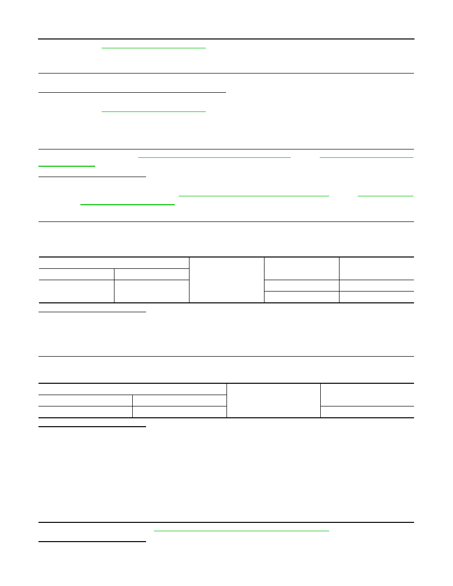
Check voltage between shift lock relay vehicle side harness connector terminal and ground.
Is the inspection result normal?
YES
>> GO TO 7.
NO-1
>> When depressing the brake pedal, the voltage is 0 V: GO TO 3.
NO-2
>> When releasing the brake pedal, the voltage is battery voltage: GO TO 5.
3.
CHECK POWER SOURCE
1.
Disconnect stop lamp switch connector.
2.
Check voltage between stop lamp switch vehicle side harness connector terminal and ground.
Is the inspection result normal?
YES
>> GO TO 4.
NO
>>
Check the following. If NG, repair or replace damaged parts.
• 10 A fuse [No. 7, located in the fuse block (J/B)]
• Harness for short to ground or open between battery and stop lamp switch vehicle side harness
connector terminal 3.
• Harness for short to ground or open between battery and stop lamp switch vehicle side harness
connector terminal 1.
• Harness for short to ground between battery and ICC brake hold relay vehicle side harness con-
nector terminal 3. (With ICC)
4.
CHECK STOP LAMP SWITCH
Check stop lamp switch. Refer to
TM-99, "Component Inspection (Stop lamp switch)"
.
Is the inspection result normal?
YES
>>
Check the following. If NG, repair or replace damaged parts.
Shift lock relay vehicle side harness connector
Ground
Condition
Voltage (Approx.)
Connector
Terminal
E52
2
Depressed brake pedal.
Battery voltage
Released brake pedal.
0 V
Stop lamp switch vehicle side harness connector
Ground
Voltage (Approx.)
Connector
Terminal
E110
3
Battery voltage
SHIFT LOCK SYSTEM
TM-97
< COMPONENT DIAGNOSIS >
[5AT: RE5R05A]
C
E
F
G
H
I
J
K
L
M
A
B
TM
N
O
P
• Harness for short to ground or open between stop lamp switch vehicle side harness connector
terminal 4 and shift lock relay vehicle side harness connector terminal 2.
• Harness for short to ground between stop lamp switch vehicle side harness connector terminal
4 and ICC brake hold relay vehicle side harness connector terminal 5. (With ICC)
NO
>> Repair or replace damaged parts.
5.
CHECK STOP LAMP SWITCH
Check stop lamp switch. Refer to
TM-99, "Component Inspection (Stop lamp switch)"
.
Is the inspection result normal?
YES-1 >> Without ICC: Repair or replace harness between stop lamp switch and shift lock relay.
YES-2 >> With ICC: GO TO 6.
NO
>> Repair or replace damaged parts.
6.
CHECK DTC WITH ICC
With CONSULT-III
Select “Self Diagnostic Results” mode for “ICC”. Refer to
CCS-24, "CONSULT-III Function (ICC)"
.
Is any malfunction detected?
YES
>> Check the DTC detected item. Refer to
CCS-24, "CONSULT-III Function (ICC)"
NO
>> Repair or replace harness between stop lamp switch and shift lock relay.
7.
CHECK GROUND CIRCUIT
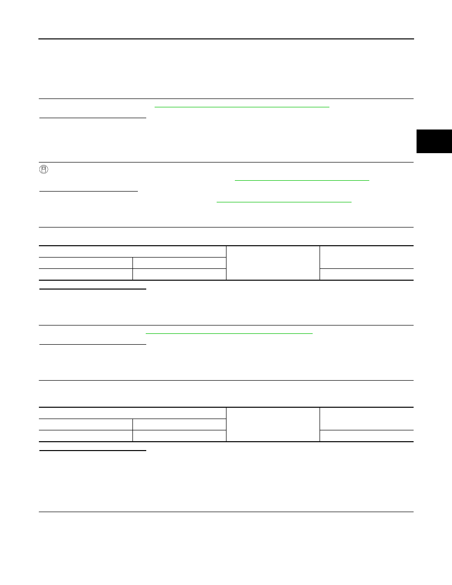
Check continuity between shift lock relay vehicle side harness connector terminal and ground.
Is the inspection result normal?
YES
>> GO TO 8.
NO
>> Repair or replace damaged parts.
8.
CHECK SHIFT LOCK RELAY
Check shift lock relay. Refer to
TM-98, "Component Inspection (Shift lock relay)"
.
Is the inspection result normal?
YES
>> GO TO 9.
NO
>> Repair or replace damaged parts.
9.
CHECK POWER SOURCE
1.
Turn ignition switch ON.
2.
Check voltage between shift lock relay vehicle side harness connector terminal and ground.
Is the inspection result normal?
YES
>> GO TO 10.
NO
>>
Check the following. If NG, repair or replace damaged parts.
• 10 A fuse [No. 3, located in the fuse block (J/B)]
• Harness for short to ground or open between ignition switch and shift lock relay vehicle side har-
ness connector terminal 5
10.
CHECK GROUND CIRCUIT
1.
Turn ignition switch OFF.
2.
Disconnect control device connector.
3.
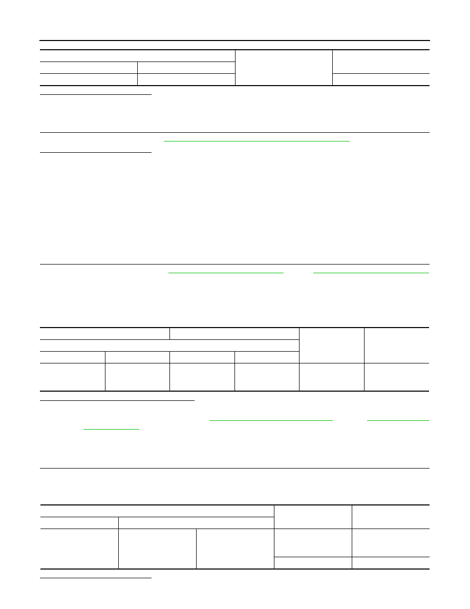
Check continuity between control device vehicle side harness connector terminal and ground.
Shift lock relay vehicle side harness connector
Ground
Continuity
Connector
Terminal
E52
1
Existed
Shift lock relay vehicle side harness connector
Ground
Voltage (Approx.)
Connector
Terminal
E52
5
Battery voltage
TM-98
< COMPONENT DIAGNOSIS >
[5AT: RE5R05A]
SHIFT LOCK SYSTEM
Is the inspection result normal?
YES
>> GO TO 11.
NO
>> Repair or replace damaged parts.
11.
CHECK SHIFT LOCK SOLENOID
Check shift lock solenoid. Refer to
TM-98, "Component Inspection (Shift lock solenoid)"
.
Is the inspection result normal?
YES
>>
Check the following. If NG, repair or replace damaged parts.
• Harness for short to ground, short to power or open between shift lock relay vehicle side har-
ness connector terminal 3 and control device vehicle side harness connector terminal 8
• Harness for short to ground, short to power or open between control device harness conductor
terminal 8 and shift lock unit harness connector terminal 3
• Harness for open between control device harness conductor terminal 4 and shift lock unit har-
ness connector terminal 4
NO
>> Repair or replace damaged parts.
Component Inspection (Shift lock solenoid)
INFOID:0000000003130567
1.
CHECK SHIFT LOCK SOLENOID
1.
Remove shift lock unit. Refer to
(AWD).
2.
Apply voltage to terminals 3 and 4 of shift lock unit connector, and then check that shift lock solenoid is
activated.
CAUTION:
Connect the fuse between the terminals when applying the voltage.
Can the lock plate be moved up and down?
YES
>> INSPECTION END
NO
>> Replace shift lock unit. Refer to
(2WD),
(AWD).
Component Inspection (Shift lock relay)
INFOID:0000000003130568
1.
CHECK SHIFT LOCK RELAY
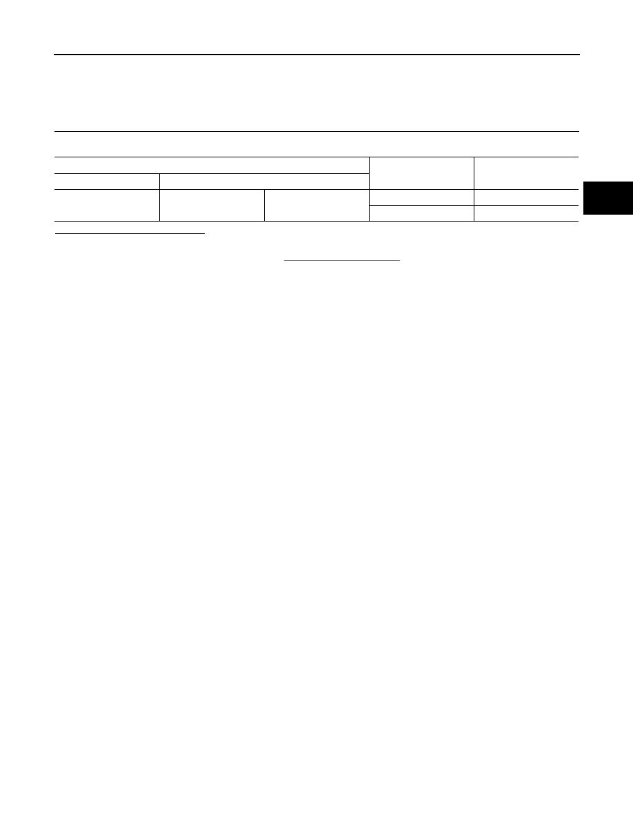
Check continuity between shift lock relay terminal 3 and 5.
CAUTION:
Connect the fuse between the terminals when applying the voltage.
Is the inspection result normal?
Control device vehicle side harness connector
Ground
Continuity
Connector
Terminal
M137
4
Existed
(+) (fuse)
(
−
)
Condition
Status
Shift lock unit connector
Connector
Terminal
Connector
Terminal
M222
3
M222
4
Apply 12 V direct
current between ter-
minals 3 and 4.
Shift lock solenoid
operates
Shift lock relay connector
Condition
Continuity
Connector
Terminal
E52
3
5
Apply 12 V direct current
between terminals 1 and
2.
Existed
OFF
Not existed
SHIFT LOCK SYSTEM
TM-99
< COMPONENT DIAGNOSIS >
[5AT: RE5R05A]
C
E
F
G
H
I
J
K
L
M
A
B
TM
N
O
P
YES
>> INSPECTION END
NO
>> Replace shift lock relay.
Component Inspection (Stop lamp switch)
INFOID:0000000003130569
1.
CHECK STOP LAMP SWITCH
Check continuity between stop lamp switch connector terminal 3 and 4.
Is the inspection result normal?
YES
>> INSPECTION END
NO
>> Replace stop lamp switch. Refer to
.
Stop lamp switch connector
Condition
Continuity
Connector
Terminal
E110
3
4
Brake pedal depressed
Existed
Brake pedal released
Not existed
Нет комментариевНе стесняйтесь поделиться с нами вашим ценным мнением.
Текст