Infiniti EX35. Manual — part 1428

TM-100
< COMPONENT DIAGNOSIS >
[5AT: RE5R05A]
SELECTOR LEVER POSITION INDICATOR
SELECTOR LEVER POSITION INDICATOR
Description
INFOID:0000000003130570
Indicates selector lever position.
Component Function Check
INFOID:0000000003130571
1.
CHECK SELECTOR LEVER POSITION INDICATOR (STEP 1)
1.
Turn ignition switch ON.
2.
Check that each position indicator lamp of the selector lever position indicator turns on when shifting the
selector lever from “P” to “M” position.
Is the inspection result normal?
YES
>> GO TO 2.
NO
>> Go to
2.
CHECK SELECTOR LEVER POSITION INDICATOR (STEP 2)
Check that the night illumination of the selector lever position indicator turns on when setting the lighting
switch in 1st position.
Is the inspection result normal?
YES
>> INSPECTION END
NO
>> Go to
Diagnosis Procedure
INFOID:0000000003130572
1.
CHECK MALFUNCTIONING ITEM
Which item is abnormal?
Position indicator lamp>>GO TO 2.
Illumination lamp>>GO TO 8.
2.
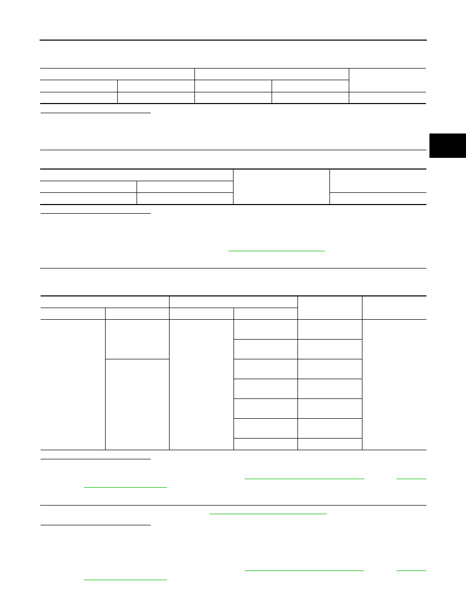
CHECK POWER SOURCE
1.
Turn ignition switch OFF.
2.
Disconnect control device connector.
3.
Turn ignition switch ON.
4.
Check voltage between control device vehicle side harness connector terminals.
Is the inspection result normal?
YES
>> GO TO 6.
NO
>> GO TO 3.
3.
CHECK GROUND CIRCUIT
Check continuity between control device vehicle side harness connector terminal and ground.
Is the inspection result normal?
YES
>> GO TO 4.
NO
>> Repair or replace damaged parts.
4.
CHECK HARNESS BETWEEN CONTROL DEVICE AND BCM (STEP 1)
1.
Disconnect BCM connector.
Control device vehicle side harness connector
Voltage (Approx.)
Connector
Terminal
Terminal
M137
10
4
Battery voltage
Control device vehicle side harness connector
Ground
Continuity
Connector
Terminal
M137
4
Existed
SELECTOR LEVER POSITION INDICATOR
TM-101
< COMPONENT DIAGNOSIS >
[5AT: RE5R05A]
C
E
F
G
H
I
J
K
L
M
A
B
TM
N
O
P
2.
Check continuity between control device vehicle side harness connector terminal and BCM vehicle side
harness connector terminal.
Is the inspection result normal?
YES
>> GO TO 5.
NO
>> Repair or replace damaged parts.
5.
CHECK HARNESS BETWEEN CONTROL DEVICE AND BCM (STEP 2)
Check continuity between control device vehicle side harness connector terminal and ground.
Is the inspection result normal?
YES
>>
Check the following.
• Check terminals of BCM connector and control device harness connector for damage.
• Check connector for loose connection.
NO
>> Check BCM input/output signal. Refer to
.
6.
CHECK SHIFT POSITION SWITCH
Check continuity between control device harness connector terminals and selector lever position indicator
connector terminals.
Is the inspection result normal?
YES
>> GO TO 7.
NO
>> Repair or replace damaged parts. Refer to
(AWD).
7.
CHECK SELECTOR LEVER POSITION INDICATOR
Check selector lever position indicator. Refer to
TM-102, "Component Inspection"
Is the inspection result normal?
YES
>>
Check the following.
• Check terminals of control device harness connector and selector lever position indicator con-
nector for damage.
• Check connector for loose connection.
NO
>> Repair or replace damaged parts. Refer to
(AWD).
Control device harness connector
BCM vehicle side harness connector
Continuity
Connector
Terminal
Connector
Terminal
M137
10
M122
96
Existed
Control device harness connector
Ground
Continuity
Connector
Terminal
M137
10
Not existed
Control device harness connector
selector lever position indicator connector
Condition
Continuity
Connector
Terminal
Connector
Terminal
M137
4
M221
7
Selector lever in “D”
position.
Existed
9
Selector lever in “M”
position.
10
2
Selector lever in “N”
position.
3
Selector lever in “D”
position.
4
Selector lever in “R”
position.
5
Selector lever in “P”
position.
6
—
TM-102
< COMPONENT DIAGNOSIS >
[5AT: RE5R05A]
SELECTOR LEVER POSITION INDICATOR
8.
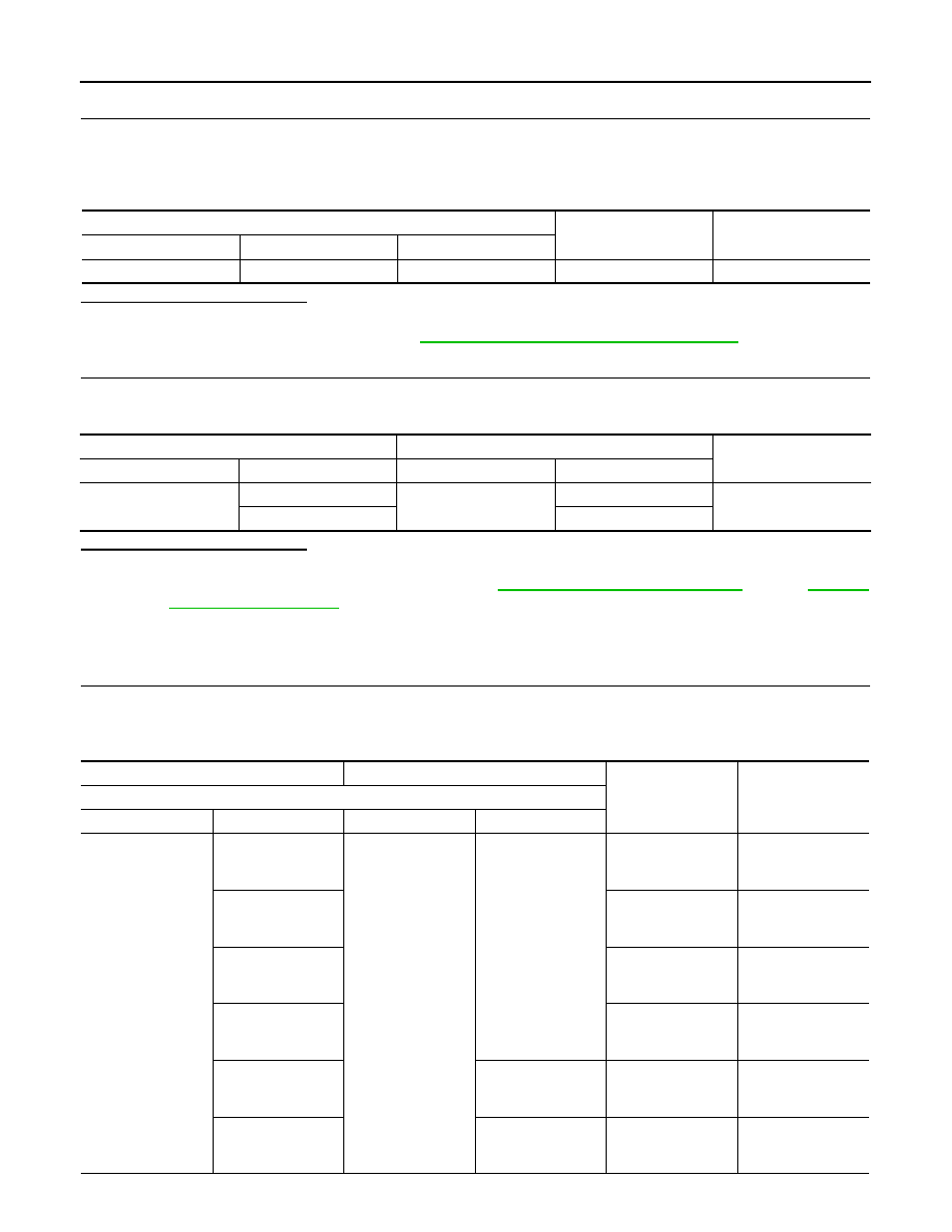
CHECK POWER SOURCE
1.
Turn ignition switch OFF.
2.
Disconnect control device connector.
3.
Turn ignition switch ON.
4.
Check voltage between control device vehicle side harness connector terminals.
Is the inspection result normal?
YES
>> GO TO 9.
NO
>> Check illumination circuit. Refer to
INL-37, "Wiring Diagram - ILLUMINATION -"
.
9.
CHECK SHIFT POSITION SWITCH
Check continuity between control device harness connector terminals and selector lever position indicator
connector terminals.
Is the inspection result normal?
YES
>> GO TO 7.
NO
>> Repair or replace damaged parts. Refer to
(AWD).
Component Inspection
INFOID:0000000003130573
1.
CHECK SELECTOR LEVER POSITION INDICATOR
Check that selector lever position indicator lamps turn on.
CAUTION:
Connect the fuse between the terminals when applying the voltage.
Control device vehicle side harness connector
Condition
Voltage (Approx.)
Connector
Terminal
Terminal
M137
7
9
Lighting switch 1ST
Battery voltage
Control device harness connector
selector lever position indicator connector
Continuity
Connector
Terminal
Connector
Terminal
M137
7
M221
10
Existed
9
11
(+) (fuse)
(
−
)
Condition
Status
Selector lever position indicator connector
Connector
Terminal
Connector
Terminal
M221
2
M221
7
Apply 12 V direct
current between ter-
minals 2 and 7.
“N” position indica-
tor lamp turns on.
3
Apply 12 V direct
current between ter-
minals 3 and 7.
“D” position indica-
tor lamp turns on.
4
Apply 12 V direct
current between ter-
minals 4 and 7.
“R” position indica-
tor lamp turns on.
5
Apply 12 V direct
current between ter-
minals 5 and 7.
“P” position indica-
tor lamp turns on.
6
9
Apply 12 V direct
current between ter-
minals 6 and 9.
“M” mode indicator
lamp turns on.
10
11
Apply 12 V direct
current between ter-
minals 10 and 11.
Illumination lamp
turns on.
Нет комментариевНе стесняйтесь поделиться с нами вашим ценным мнением.
Текст