Infiniti EX35. Manual — part 853
FL-10
< ON-VEHICLE REPAIR >
FUEL TANK
FUEL TANK
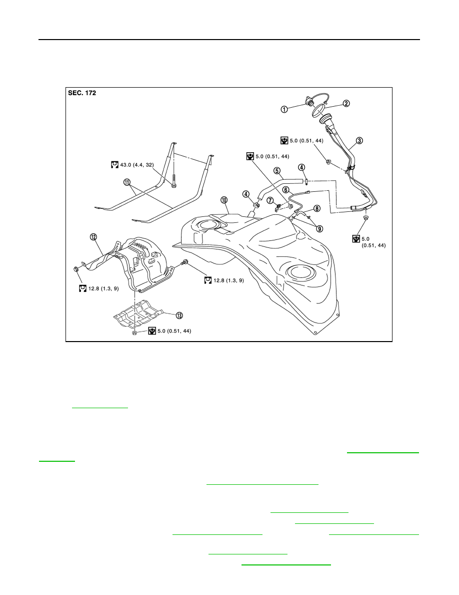
Exploded View
INFOID:0000000003136992
Removal and Installation
INFOID:0000000003136993
WARNING:
Be sure to read “General Precautions” when working on the fuel system. Refer to
.
REMOVAL
• Drain fuel from fuel tank if necessary. Refer to
FL-5, "Removal and Installation"
.
• Perform work on level place.
1.
Perform steps 2 to 7 of “REMOVAL” in “ FUEL LEVEL SENSOR UNIT, FUEL FILTER AND FUEL PUMP
ASSEMBLY” on main and sub fuel level sensor units. Refer to
2.
Remove exhaust front tube, center muffler and main muffler. Refer to
.
3.
Remove propeller shaft. Refer to
(2WD models) or
(AWD models).
4.
Remove parking rear brake cables. Refer to
.
5.
Remove rear suspension member assembly. Refer to
.
1.
Fuel filler cap
2.
Grommet
3.
Fuel filler tube
4.
Clamp
5.
Fuel filler hose
6.
EVAP tube
7.
Clamp
8.
Vent hose
9.
Clamp
10. Fuel tank
11.
Fuel tank mounting band
12. Fuel tank protector
13. Insulator
Refer to
for symbols in the figure.
JPBIA1837GB
FUEL TANK
FL-11
< ON-VEHICLE REPAIR >
C
D
E
F
G
H
I
J
K
L
M
A
FL
N
P
O
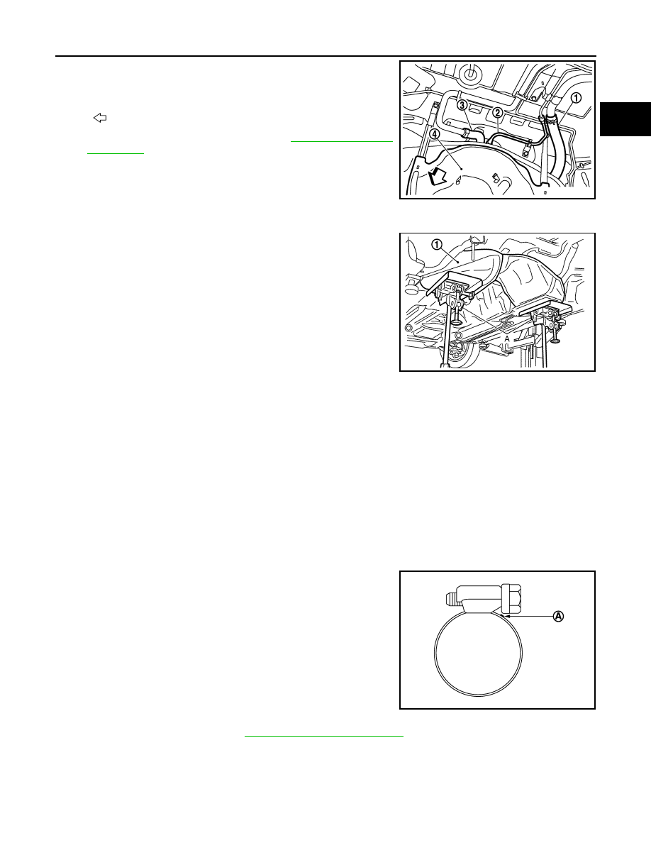
6.
Disconnect fuel filler hose (1), EVAP tube (2) and vent hoses (3)
at fuel tank side.
• To disconnect quick connector, refer to
.
7.
Remove fuel tank protector.
8.
Support the lower part of fuel tank (1) with transmission jack (A).
CAUTION:
Support the position that fuel tank mounting bands never
engage.
9.
Remove fuel tank mounting bands.
10. Supporting with hands, descend transmission jack carefully, and remove fuel tank.
CAUTION:
• Check that all connection points have been disconnected.
• Confirm there is no interference with vehicle.
11. Remove fuel filler tube, as necessary.
INSTALLATION
Note the following, and install in the reverse order of removal.
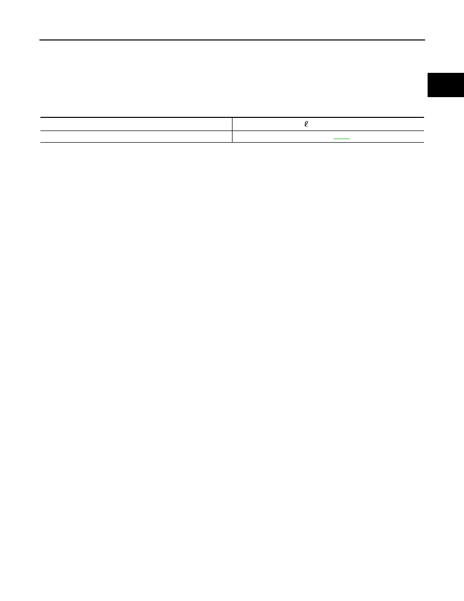
• Surely clamp fuel hoses and insert hose to the length below.
• Be sure hose clamp is not placed on swelled area of fuel tube.
• Tighten the clamp hand with the top mark (A) until the mark is on
the bolt head flange.
• To connect quick connector, refer to
FL-5, "Removal and Installation"
Inspection
INFOID:0000000003136994
INSPECTION AFTER INSTALLATION
Use the following procedure to check for fuel leakage.
4
: Fuel tank protector
: Vehicle front
JPBIA1838ZZ
JPBIA0145ZZ
Fuel filler hose
: 35 mm (1.38 in)
The other hoses
: 25 mm (0.98 in)
JPBIA0146ZZ
FL-12
< ON-VEHICLE REPAIR >
FUEL TANK
1.
Turn ignition switch “ON” (with engine stopped), and check connections for leakage by applying fuel pres-
sure to fuel piping.
2.
Start engine and rev it up and check there are no fuel leakage at the fuel system tube and hose connec-
tions.
• After removing/installing rear suspension assembly, check to adjust wheel alignment. Refer to
SERVICE DATA AND SPECIFICATIONS (SDS)
FL-13
< SERVICE DATA AND SPECIFICATIONS (SDS)
C
D
E
F
G
H
I
J
K
L
M
A
FL
N
P
O
SERVICE DATA AND SPECIFICATIONS (SDS)
SERVICE DATA AND SPECIFICATIONS (SDS)
Fuel Tank
INFOID:0000000003136998
Standard and Limit
Fuel tank capacity
Approx. 76 (20 US gal, 16-5/8 Imp gal)
Fuel recommendation
Refer to
Нет комментариевНе стесняйтесь поделиться с нами вашим ценным мнением.
Текст