Infiniti EX35. Manual — part 540
DLN-110
< DISASSEMBLY AND ASSEMBLY >
[FRONT FINAL DRIVE: F160A]
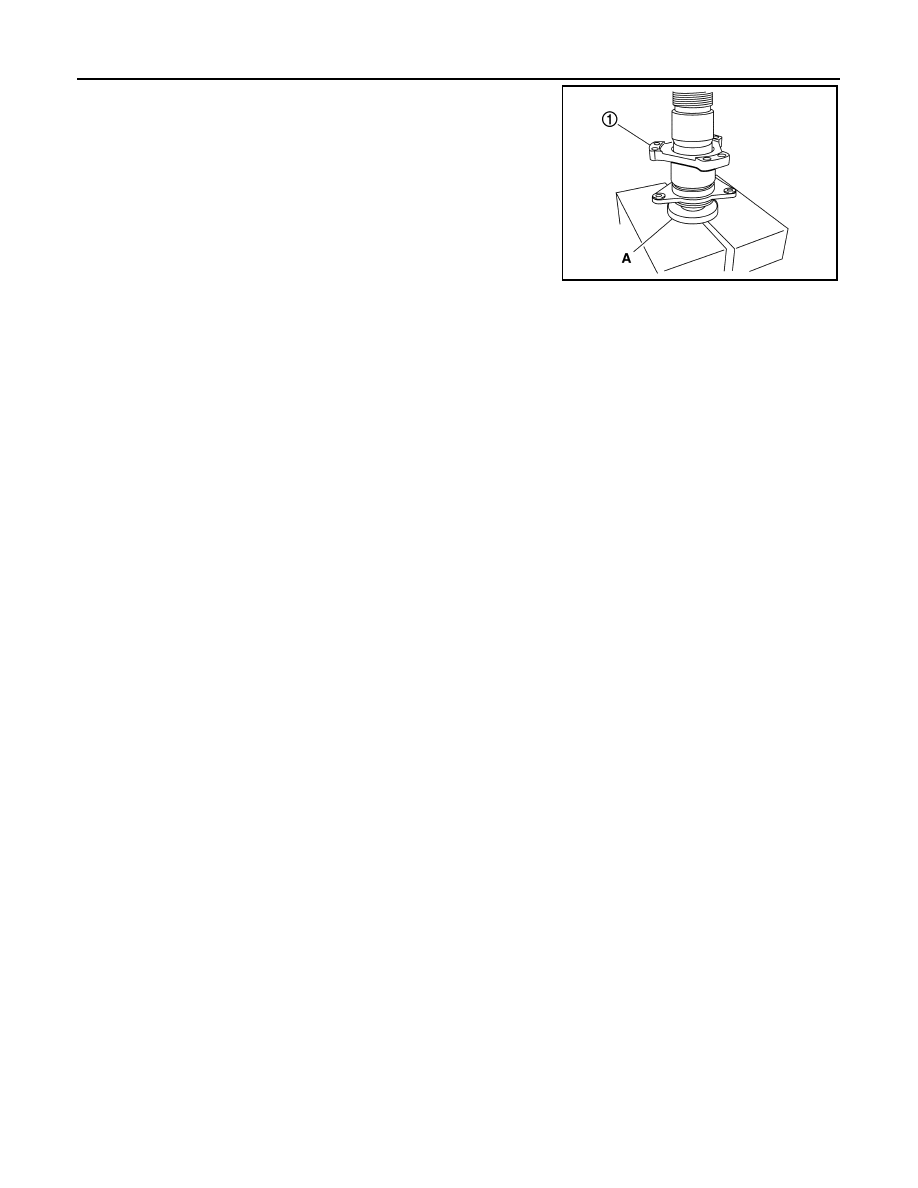
SIDE SHAFT
3.
Support side shaft bearing with the drift (A) [SST: ST30032000
(J-26010-01)], then press side shaft (1) into the side shaft bear-
ing using a press.
4.
Apply multi-purpose grease to O-ring, and install it to extension
tube retainer.
CAUTION:
Never reuse O-ring.
Inspection After Disassembly
INFOID:0000000003135794
DRIVE GEAR AND DRIVE PINION
• Clean up the disassembled parts.
• If the gear teeth never mesh or line-up correctly, determine the cause and adjust or replace as necessary.
• If the gears are worn, cracked, damaged, pitted or chipped (by friction) noticeably, replace with new drive
gear and drive pinion as a set.
BEARING
• Clean up the disassembled parts.
• If any chipped (by friction), pitted, worn, rusted or scratched marks, or unusual noise from the bearing is
observed, replace as a bearing assembly (as a new set).
SIDE GEAR AND PINION MATE GEAR
• Clean up the disassembled parts.
• If any cracks or damage on the surface of the tooth is found, replace.
• If any worn or chipped mark on the contact sides of the thrust washer is found, replace.
SIDE GEAR THRUST WASHER AND PINION MATE THRUST WASHER
• Clean up the disassembled parts.
• If it is chipped (by friction), damaged, or unusually worn, replace.
OIL SEAL
• Whenever disassembled, replace.
• If wear, deterioration of adherence (sealing force lips), or damage is detected on the lips, replace them.
DIFFERENTIAL CASE
• Clean up the disassembled parts.
• If any wear or crack on the contact sides of the differential case is found, replace.
COMPANION FLANGE
• Clean up the disassembled parts.
• If any chipped mark [about 0.1 mm, (0.004 in)] or other damage on the contact sides of the lips of the com-
panion flange is found, replace.
PDIA0815J
DIFFERENTIAL ASSEMBLY
DLN-111
< DISASSEMBLY AND ASSEMBLY >
[FRONT FINAL DRIVE: F160A]
C
E
F
G
H
I
J
K
L
M
A
B
DLN
N
O
P
DIFFERENTIAL ASSEMBLY
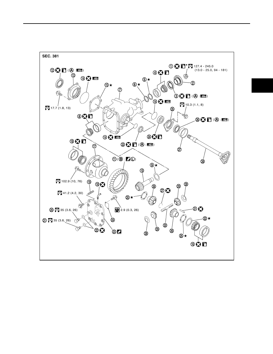
Exploded View
INFOID:0000000003135795
1.
Drive pinion lock nut
2.
Companion flange
3.
Front oil seal
4.
Pinion front bearing
5.
Drive pinion bearing adjusting wash-
er
6.
Drive pinion adjusting washer
7.
Gear carrier
8.
Pinion rear bearing
9.
Pinion height adjusting washer
10. Drive pinion
11.
Drive gear
12. Side oil seal (right side)
13. Side retainer
14. O-ring
15. Side bearing adjusting shim
16. Side bearing
17. Differential case
18. Breather connector
19. Dowel pin
20. Filler plug
21. Drain plug
22. Gasket
23. Carrier cover
24. Gear oil defense
25. Side gear thrust washer
26. Side gear
27. Circular clip
28. Pinion mate thrust washer
29. Pinion mate gear
30. Pinion mate shaft
31. Lock pin
32. Side bearing adjusting washer
33. Side oil seal (left side)
JSDIA0020GB
DLN-112
< DISASSEMBLY AND ASSEMBLY >
[FRONT FINAL DRIVE: F160A]
DIFFERENTIAL ASSEMBLY
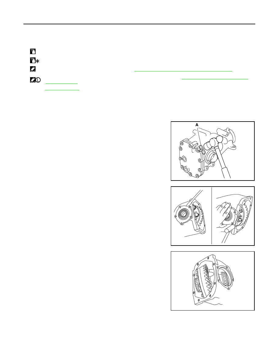
Disassembly
INFOID:0000000003135796
1.
Drain gear oil, if necessary.
2.
Remove carrier cover mounting bolts.
3.
Remove carrier cover to insert the seal cutter (A) [SST:
KV10111100 (J-37228)] between gear carrier and carrier cover.
CAUTION:
• Never damage the mating surface.
• Never insert flat-bladed screwdriver, this may damage the
mating surface.
4.
Remove side retainer.
5.
Remove side bearing adjusting shim.
6.
Remove O-ring from side retainer.
7.
Remove differential case assembly from gear carrier.
34. Side shaft bearing
35. Extension tube retainer
36. Side shaft oil seal
37. Dust seal
38. Side shaft
A:
Oil seal lip
B:
Screw hole
:
Apply gear oil.
:
Apply anti-corrosion oil.
:
Apply Genuine Silicone RTV or equivalent. Refer to
GI-15, "Recommended Chemical Products and Sealants"
:
Apply Genuine Medium Strength Thread Locking Sealant or equivalent. Refer to
GI-15, "Recommended Chemical Prod-
.
Refer to
for symbols not described above.
PDIA0795J
PDIA0670E
PDIA0671E
DIFFERENTIAL ASSEMBLY
DLN-113
< DISASSEMBLY AND ASSEMBLY >
[FRONT FINAL DRIVE: F160A]
C
E
F
G
H
I
J
K
L
M
A
B
DLN
N
O
P
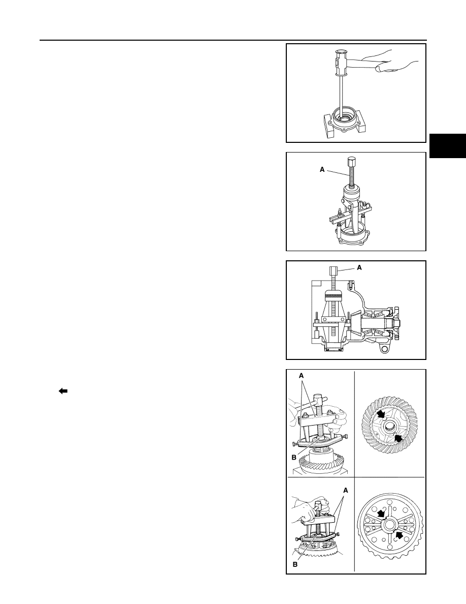
8.
Remove side oil seal (right side) from side retainer.
9.
Remove side bearing outer race with puller (A) [SST:
KV381054S0 (J-34286)].
10. Remove O-ring from gear carrier.
11. Remove side oil seal (left side) from gear carrier.
12. Remove side bearing outer race with puller (A) [SST:
KV381054S0 (J-34286)].
13. Remove side bearing inner race.
To prevent damage to bearing, engage puller jaws in groove
(
).
CAUTION:
• To prevent damage to the side bearing and drive gear,
place copper plates between these parts and vise.
• It is not necessary to remove side bearing inner race
except if it is replaced.
PDIA0672E
PDIA0796J
PDIA0797J
A: Puller [SST: ST33051001 (J-22888-20)]
B: Base [SST: ST33061000 (J-8107-2)]
PDIA0758J
Нет комментариевНе стесняйтесь поделиться с нами вашим ценным мнением.
Текст