Infiniti EX35. Manual — part 539
DLN-106
< REMOVAL AND INSTALLATION >
[FRONT FINAL DRIVE: F160A]
FRONT FINAL DRIVE ASSEMBLY
REMOVAL AND INSTALLATION
FRONT FINAL DRIVE ASSEMBLY
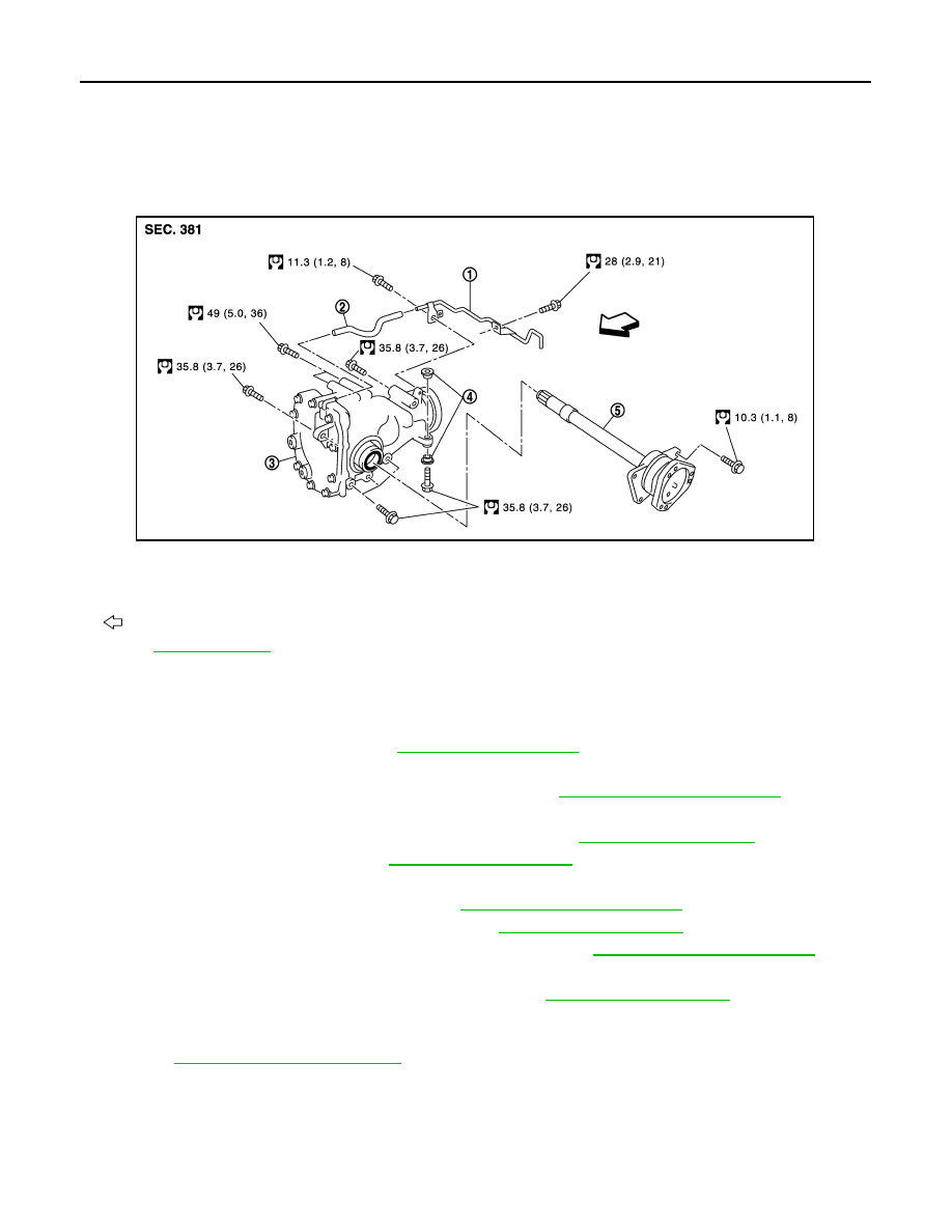
Exploded View
INFOID:0000000003135789
Removal and Installation
INFOID:0000000003135790
REMOVAL
1.
Remove both front drive shaft. Refer to
.
2.
Remove front crossbar with power tool.
3.
Separate steering outer socket and steering knuckle. Refer to
.
4.
Remove side shaft.
5.
Remove three way catalyst (right bank) with power tool. Refer to
6.
Remove front propeller shaft. Refer to
.
7.
Separate power steering solenoid valve connector.
8.
Separate power steering hydraulic line. Refer to
.
9.
Remove stabilizer assembly with power tool. Refer to
10. Separate steering lower joint and steering gear assembly. Refer to
.
11. Set a suitable jack to engine.
12. Remove front suspension member with power tool. Refer to
13. Remove breather hose and tube.
14. Remove engine mounting bracket (RH) (Lower) and engine mounting insulator (RH) with power tool.
.
15. Remove final drive assembly mounting bolts with power tool and separate front final drive assembly from
engine.
INSTALLATION
Note the following, install in the reverse order of removal.
1.
Breather tube
2.
Breather hose
3.
Front final drive assembly
4.
Bushing
5.
Side shaft
: Vehicle front
Refer to
for symbols in the figure.
JPDID0206GB
FRONT FINAL DRIVE ASSEMBLY
DLN-107
< REMOVAL AND INSTALLATION >
[FRONT FINAL DRIVE: F160A]
C
E
F
G
H
I
J
K
L
M
A
B
DLN
N
O
P
• When installing the side shaft, apply multi-purpose grease to contact surface of side shaft and side shaft oil
seal.
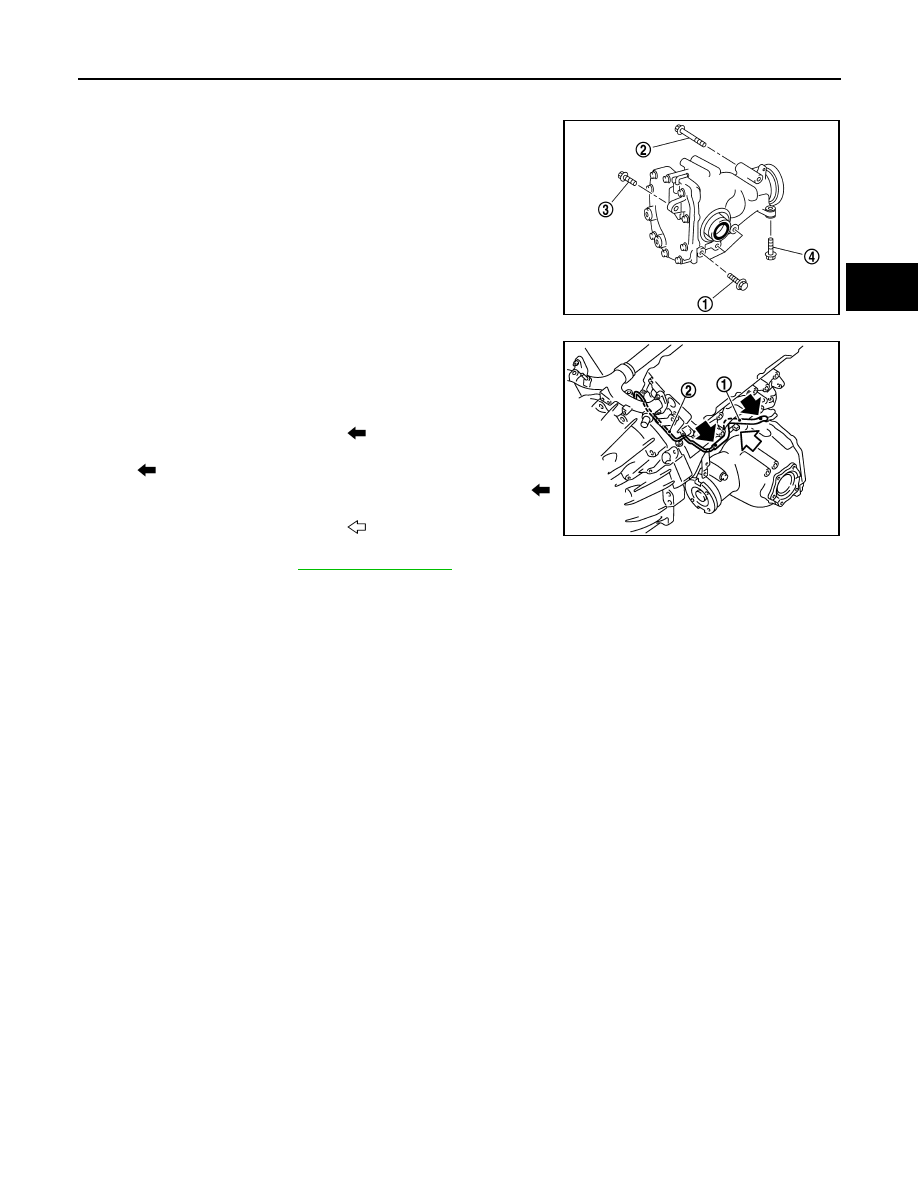
• Tighten mounting bolts in the order described below when install-
ing front final drive assembly: side of gear carrier (1), upper side of
gear carrier (2), part of carrier cover (3), lower part of gear carrier
(4).
CAUTION:
Align the mating faces of gear carrier and oil pan for installa-
tion.
• When installing breather hose (1) and tube (2), refer to the figure.
CAUTION:
Make sure there are no pinched or restricted areas on the
breather hose caused by bending or winding when installing
it.
- Make sure the paint mark facing up (
).
- Securely install the hose until it seats the rounded portion of the
tube. (
) (front final drive assembly side).
- Securely install the hose until it to paint mark of the tube. (
)
(vehicle rear side).
- Face the bend of the breather hose (
) to the engine.
• When oil leaks while removing final drive assembly, check oil level
after the installation. Refer to
PDIA0839J
JSDIA0018ZZ

DLN-108
< DISASSEMBLY AND ASSEMBLY >
[FRONT FINAL DRIVE: F160A]
SIDE SHAFT
DISASSEMBLY AND ASSEMBLY
SIDE SHAFT
Exploded View
INFOID:0000000003135791
1.
Drive pinion lock nut
2.
Companion flange
3.
Front oil seal
4.
Pinion front bearing
5.
Drive pinion bearing adjusting wash-
er
6.
Drive pinion adjusting washer
7.
Gear carrier
8.
Pinion rear bearing
9.
Pinion height adjusting washer
10. Drive pinion
11.
Drive gear
12. Side oil seal (right side)
13. Side retainer
14. O-ring
15. Side bearing adjusting shim
16. Side bearing
17. Differential case
18. Breather connector
19. Dowel pin
20. Filler plug
21. Drain plug
22. Gasket
23. Carrier cover
24. Gear oil defense
25. Side gear thrust washer
26. Side gear
27. Circular clip
28. Pinion mate thrust washer
29. Pinion mate gear
30. Pinion mate shaft
JSDIA0020GB
SIDE SHAFT
DLN-109
< DISASSEMBLY AND ASSEMBLY >
[FRONT FINAL DRIVE: F160A]
C
E
F
G
H
I
J
K
L
M
A
B
DLN
N
O
P
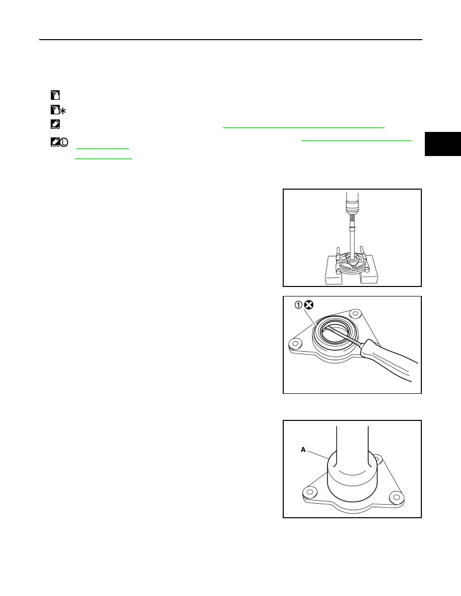
Disassembly
INFOID:0000000003135792
1.
Hold extension tube retainer with puller, then press out side
shaft using a press.
2.
Remove side shaft oil seal (1) from extension tube retainer with
a flat- blade screwdriver.
CAUTION:
Never damage extension tube retainer.
3.
Remove side shaft bearing from extension tube retainer.
4.
Remove O-ring from extension tube retainer.
5.
Remove dust seal from side shaft.
Assembly
INFOID:0000000003135793
1.
Using the drift (A) [SST: KV38100200 (
—
)], install side shaft
oil seal.
CAUTION:
• Never reuse oil seal.
• When installing, never incline oil seal.
• Apply multi-purpose grease onto oil seal lips, and gear oil
onto the circumference of oil seal.
2.
Install dust seal.
31. Lock pin
32. Side bearing adjusting washer
33. Side oil seal (left side)
34. Side shaft bearing
35. Extension tube retainer
36. Side shaft oil seal
37. Dust seal
38. Side shaft
A:
Oil seal lip
B:
Screw hole
:
Apply gear oil.
:
Apply anti-corrosion oil.
:
Apply Genuine Silicone RTV or equivalent. Refer to
GI-15, "Recommended Chemical Products and Sealants"
:
Apply Genuine Medium Strength Thread Locking Sealant or equivalent. Refer to
GI-15, "Recommended Chemical Prod-
.
Refer to
for symbols not described above.
PDIA0793J
PDIA0794J
PDIA0814J
Нет комментариевНе стесняйтесь поделиться с нами вашим ценным мнением.
Текст