Infiniti EX35. Manual — part 1182

PG-98
< COMPONENT DIAGNOSIS >
[POWER SUPPLY&GROUND CIRCUIT]
FUSE BLOCK - JUNCTION BOX (J/B)
FUSE BLOCK - JUNCTION BOX (J/B)
Fuse, Connector and Terminal Arrangement
INFOID:0000000003131938
Click here to view the eWD.
JCMWM1496GB
PG
FUSE, FUSIBLE LINK AND RELAY BOX
PG-99
< COMPONENT DIAGNOSIS >
[POWER SUPPLY&GROUND CIRCUIT]
C
D
E
F
G
H
I
J
K
L
B
A
O
P
N
FUSE, FUSIBLE LINK AND RELAY BOX
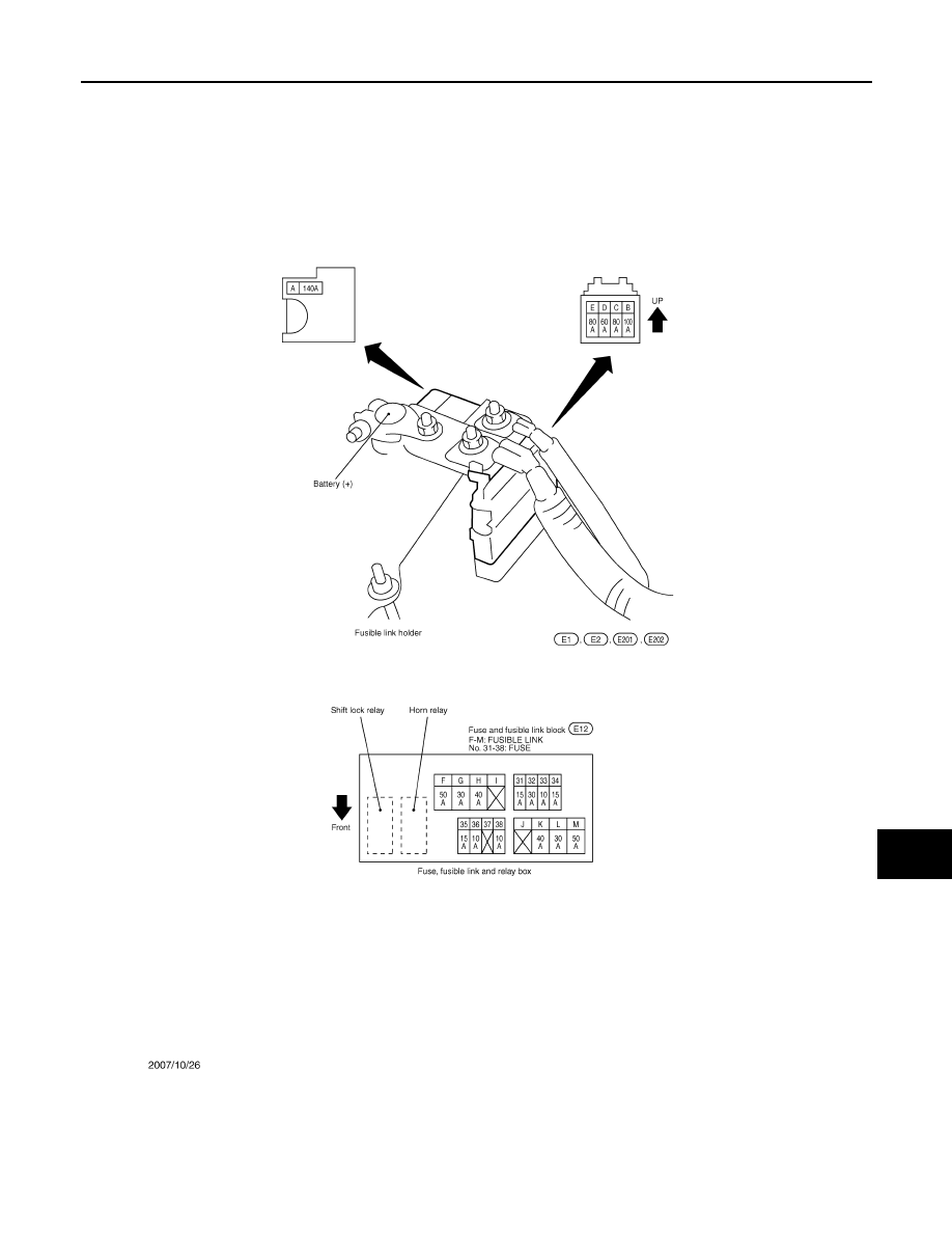
Fuse and Fusible Link Arrangement
INFOID:0000000003131939
JCMWM1497GB
PG-100
< COMPONENT DIAGNOSIS >
[POWER SUPPLY&GROUND CIRCUIT]
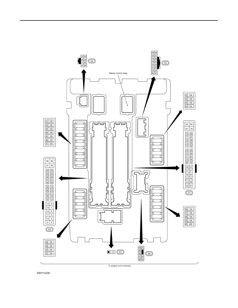
IPDM E/R (INTELLIGENT POWER DISTRIBUTION MODULE ENGINE ROOM)
IPDM E/R (INTELLIGENT POWER DISTRIBUTION MODULE ENGINE
ROOM)
Fuse, Connector and Terminal Arrangement
INFOID:0000000003131940
JCMWM1498GB
PG
PRECAUTIONS
PG-101
< PRECAUTION >
[POWER SUPPLY&GROUND CIRCUIT]
C
D
E
F
G
H
I
J
K
L
B
A
O
P
N
PRECAUTION
PRECAUTIONS
Precaution for Supplemental Restraint System (SRS) "AIR BAG" and "SEAT BELT
PRE-TENSIONER"
INFOID:0000000003131941
The Supplemental Restraint System such as “AIR BAG” and “SEAT BELT PRE-TENSIONER”, used along
with a front seat belt, helps to reduce the risk or severity of injury to the driver and front passenger for certain
types of collision. This system includes seat belt switch inputs and dual stage front air bag modules. The SRS
system uses the seat belt switches to determine the front air bag deployment, and may only deploy one front
air bag, depending on the severity of a collision and whether the front occupants are belted or unbelted.
Information necessary to service the system safely is included in the “SRS AIRBAG” and “SEAT BELT” of this
Service Manual.
WARNING:
• To avoid rendering the SRS inoperative, which could increase the risk of personal injury or death in
the event of a collision which would result in air bag inflation, all maintenance must be performed by
an authorized NISSAN/INFINITI dealer.
• Improper maintenance, including incorrect removal and installation of the SRS, can lead to personal
injury caused by unintentional activation of the system. For removal of Spiral Cable and Air Bag
Module, see the “SRS AIRBAG”.
• Do not use electrical test equipment on any circuit related to the SRS unless instructed to in this
Service Manual. SRS wiring harnesses can be identified by yellow and/or orange harnesses or har-
ness connectors.
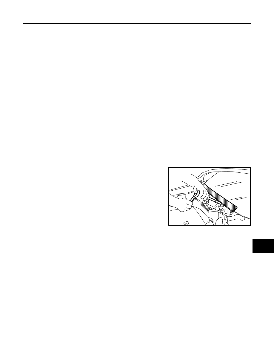
Precaution for Procedure without Cowl Top Cover
INFOID:0000000003131942
When performing the procedure after removing cowl top cover, cover
the lower end of windshield with urethane, etc.
PIIB3706J
Нет комментариевНе стесняйтесь поделиться с нами вашим ценным мнением.
Текст