Infiniti EX35. Manual — part 1183
PG-102
< PREPARATION >
[POWER SUPPLY&GROUND CIRCUIT]
PREPARATION
PREPARATION
PREPARATION
Special Service Tools
INFOID:0000000003131943
Tool number
(Kent-Moore No.)
Tool name
Description
—
(J-48087)
Battery Service Center
Tests battery.
For operating instructions, refer to Technical
Service Bulletin and Battery Service Center
User Guide.
WKIA5280E
PG
BATTERY
PG-103
< ON-VEHICLE REPAIR >
[POWER SUPPLY&GROUND CIRCUIT]
C
D
E
F
G
H
I
J
K
L
B
A
O
P
N
ON-VEHICLE REPAIR
BATTERY
Exploded View
INFOID:0000000003131944
Removal and Installation
INFOID:0000000003131945
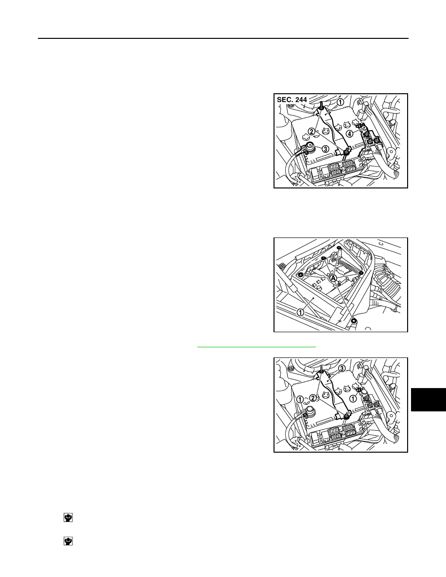
REMOVAL
1.
Remove battery cover.
2.
Remove the clips (A), and remove hoodledge cover RH (1).
3.
Remove the cowl top cover (RH). Refer to
EXT-23, "Removal and Installation"
4.
Loosen battery terminal nuts (1), and disconnect both battery
cables from battery terminals.
CAUTION:
When disconnecting, disconnect the battery cable from the
negative terminal first.
5.
Remove battery fix frame mounting nuts (2) and battery fix
frame (3).
6.
Remove battery.
INSTALLATION
Install in the reverse order of removal.
CAUTION:
When connecting, connect the battery cable to the positive terminal first.
1
: Battery fix frame
2
: Battery fix frame mounting nuts
3
: Battery terminal (-)
4
: Battery terminal (+)
JPMIA0886ZZ
JPMIA0887ZZ
JPMIA0888ZZ
Battery fix frame mounting nut
: 3.9 N·m (0.40 kg-m, 35 in-lb)
Battery terminal nut
: 5.4 N·m (0.55 kg-m, 48 in-lb)
PG-104
< ON-VEHICLE REPAIR >
[POWER SUPPLY&GROUND CIRCUIT]
BATTERY
Reset electronic systems as necessary. Refer to
GI-52, "ADDITIONAL SERVICE WHEN REMOVING BAT-
TERY NEGATIVE TERMINAL : Required Procedure After Battery Disconnection"
PG
BATTERY TERMINAL WITH FUSIBLE LINK
PG-105
< ON-VEHICLE REPAIR >
[POWER SUPPLY&GROUND CIRCUIT]
C
D
E
F
G
H
I
J
K
L
B
A
O
P
N
BATTERY TERMINAL WITH FUSIBLE LINK
Exploded View
INFOID:0000000003131946
Removal and Installation
INFOID:0000000003131947
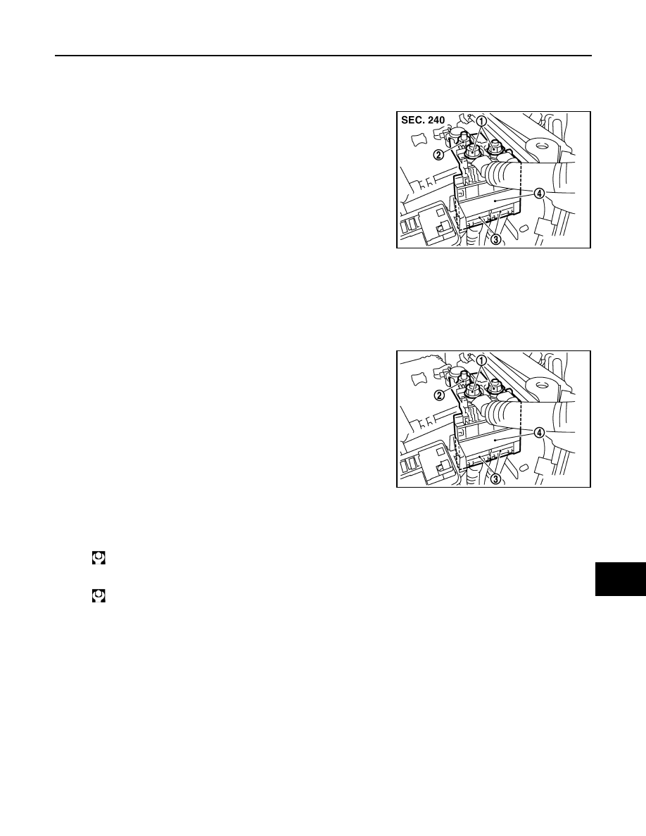
REMOVAL
1.
Remove battery cover.
2.
Disconnect the battery cable from the negative terminal.
3.
Remove cover of battery positive terminal.
4.
Remove harness mounting nuts (1) and fusible link holder
mounting nut (2).
5.
Disconnect harness connector (3) and remove battery terminal
with fusible link (4).
INSTALLATION
Install in the reverse order of removal.
1
: Harness mounting nuts
2
: Fusible link holder mounting nut
3
: Harness connector
4
: Battery terminal with fusible link
JPMIA0889ZZ
JPMIA0890ZZ
Harness mounting nut
: 13.2 N·m (1.3 kg-m, 10 ft-lb)
Fusible link holder mounting nut
: 13.2 N·m (1.3 kg-m, 10 ft-lb)
Нет комментариевНе стесняйтесь поделиться с нами вашим ценным мнением.
Текст