Infiniti EX35. Manual — part 1335
SN
SONAR CONTROL UNIT
SN-31
< ECU DIAGNOSIS >
C
D
E
F
G
H
I
J
K
L
M
B
A
O
P
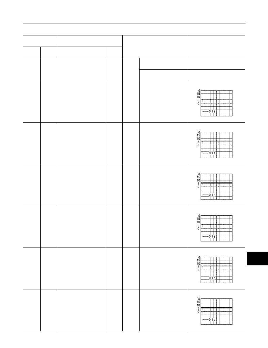
PHYSICAL VALUES
Terminal No.
(Wire color)
Description
Condition
Value
(Approx.)
+
–
Signal name
Input/
Output
2
(R)
Ground
Cancel switch signal
Input
Ignition
switch
ON
Turns ON while pressing
sonar cancel switch ON.
0 V
Other than while pressing
sonar cancel switch ON.
12.0 V
3
(R)
12
(B)
Corner sensor signal front
LH
Input
Ignition
switch
ON
Other than shift position in
P position.
4
(W)
12
(B)
Corner sensor signal front
RH
Input
Ignition
switch
ON
Other than shift position in
P position.
5
(W)
12
(B)
Corner sensor signal rear
LH
Input
Ignition
switch
ON
Shift position in R position.
6
(L)
12
(B)
Corner sensor signal rear
RH
Input
Ignition
switch
ON
Selector lever in R position.
7
(G)
12
(B)
Center sensor signal rear
LH
Input
Ignition
switch
ON
Selector lever in R position.
8
(Y)
12
(B)
Center sensor signal rear
RH
Input
Ignition
switch
ON
Selector lever in R position.
SKIB8942E
SKIB8942E
SKIB8942E
SKIB8942E
SKIB8942E
SKIB8942E
SN-32
< ECU DIAGNOSIS >
SONAR CONTROL UNIT
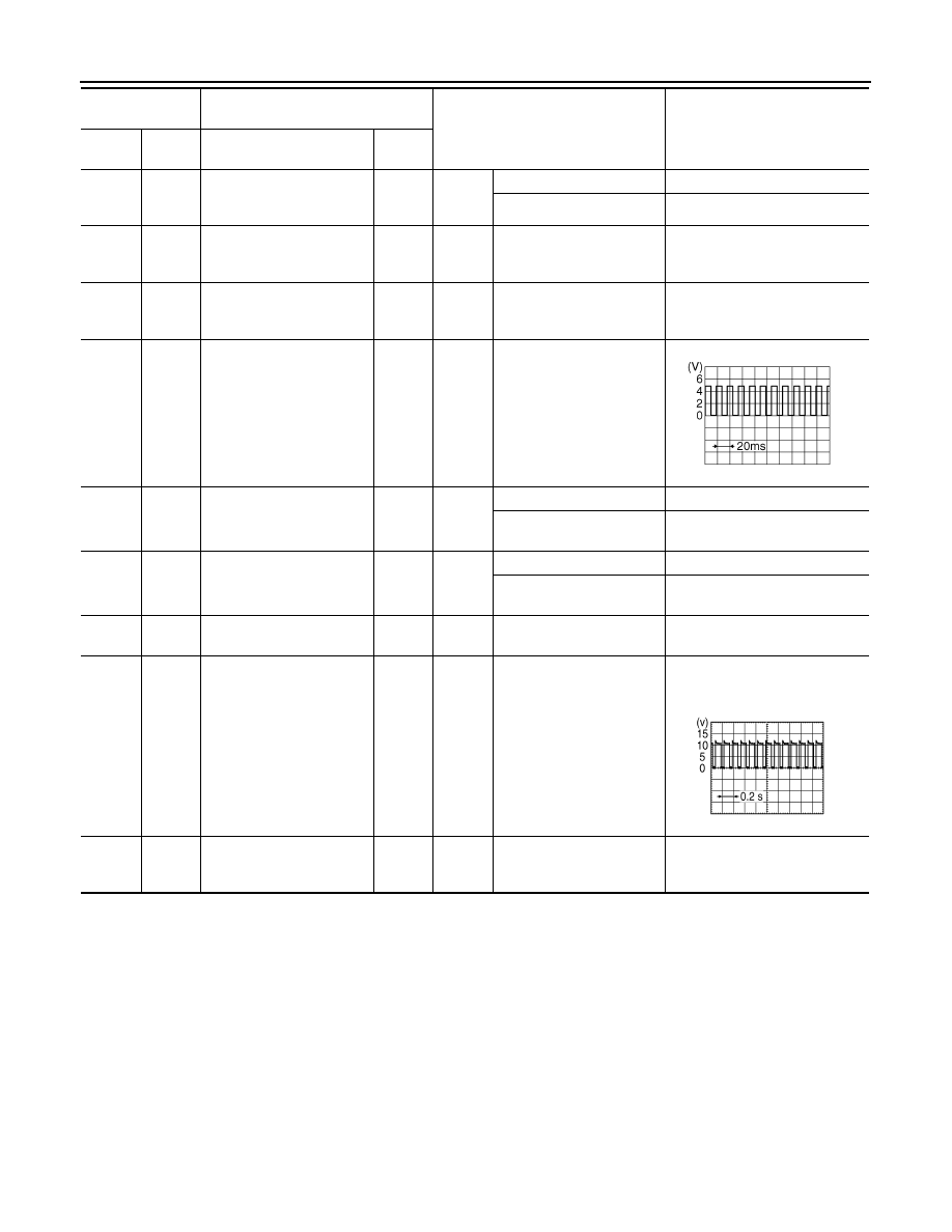
11
(W)
Ground
LED signal
Output
Ignition
switch
ON
Sonar system ON
12.0 V
Sonar system OFF
0 V
12
(B)
Ground
Sensor ground
—
Ignition
switch
ON
—
0 V
13
(V)
Ground
Ignition power supply
Input
Ignition
switch
ON
—
12.0 V
15
(G)
Ground
Vehicle speed signal
(8-pulse)
Input
Ignition
switch
ON
When vehicle speed is ap-
prox. 40 km/h (25 MPH).
16
(BR)
Ground
P range signal
Input
Ignition
switch
ON
Shift position in P position.
0 V
Other than shift position in
P position.
12.0 V
17
(BR)
Ground
Reverse range
Input
Ignition
switch
ON
Shift position in R position.
12.0 V
Other than shift position in
R position.
0 V
18
(O)
—
K-line (CONSULT-III)
—
—
—
—
23
(GR)
Ground
Buzzer drive signal
Output
Ignition
switch
ON
When buzzer operation
NOTE:
Waveform period changes due to
the distance to an obstacle.
24
(B)
Ground
Ground
—
Ignition
switch
ON
—
0 V
Terminal No.
(Wire color)
Description
Condition
Value
(Approx.)
+
–
Signal name
Input/
Output
SKIA6649J
SKIB8943E
SN
SONAR CONTROL UNIT
SN-33
< ECU DIAGNOSIS >
C
D
E
F
G
H
I
J
K
L
M
B
A
O
P
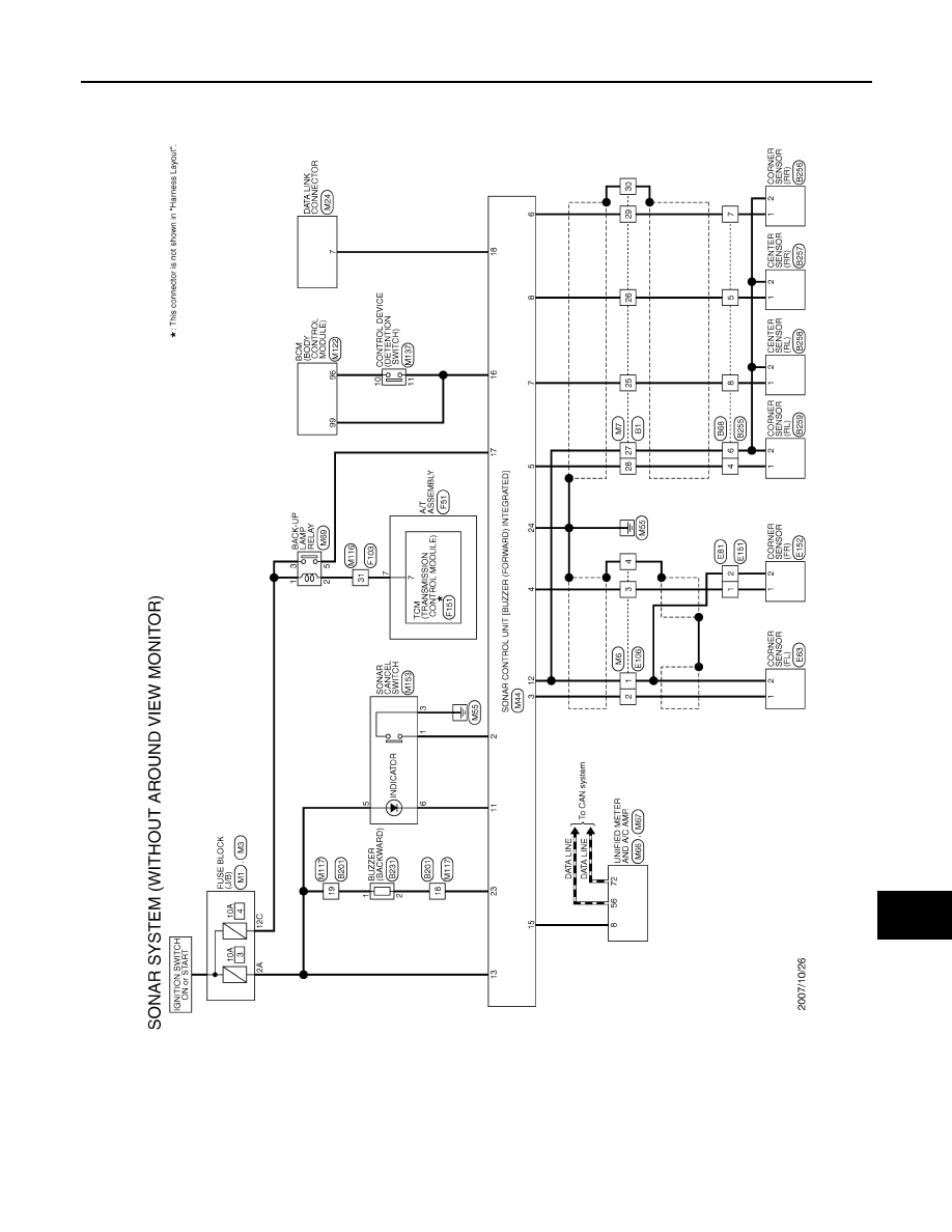
Wiring Diagram — SONAR SYSTEM —
INFOID:0000000003160582
JCNWM0725GB
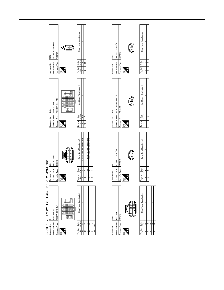
SN-34
< ECU DIAGNOSIS >
SONAR CONTROL UNIT
JCNWM0726GB
Нет комментариевНе стесняйтесь поделиться с нами вашим ценным мнением.
Текст