Infiniti EX35. Manual — part 1334
SN
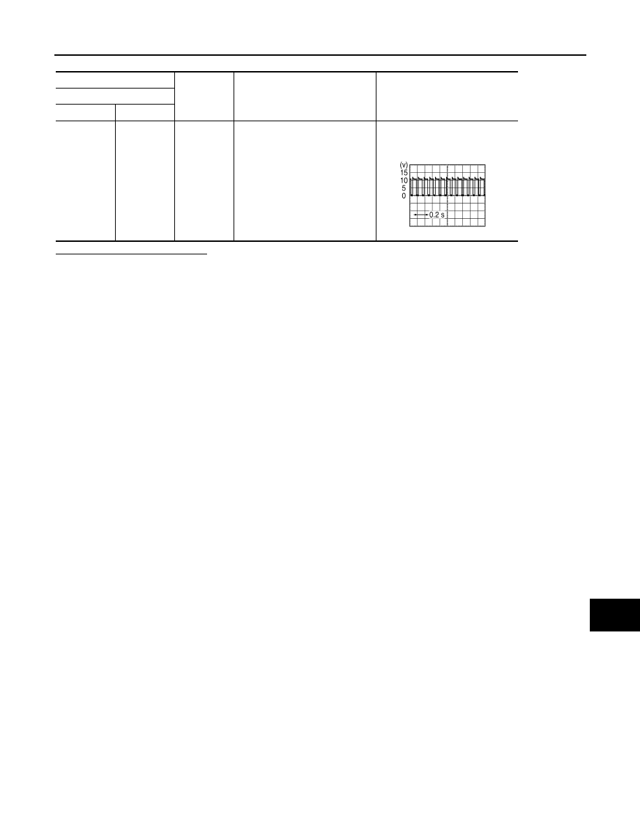
BUZZER CIRCUIT
SN-27
< COMPONENT DIAGNOSIS >
C
D
E
F
G
H
I
J
K
L
M
B
A
O
P
Is the inspection result normal?
YES
>> INSPECTION END
NO
>> Replace sonar control unit.
(+)
(
−
)
Condition
Signal
Sonar control unit
Connector
Terminal
M44
23
Ground
When buzzer operation
NOTE:
Waveform period changes due to
the distance to an obstacle.
SKIB8943E

SN-28
< COMPONENT DIAGNOSIS >
SONAR CANCEL SWITCH CIRCUIT
SONAR CANCEL SWITCH CIRCUIT
Description
INFOID:0000000003160578
The sonar control unit turns the sonar system activation OFF when inputting the cancel switch signal.
Component Function Check
INFOID:0000000003160579
1.
SONAR CONTROL UNIT DATA MONITOR INSPECTION
Check the cancel switch with the sonar control unit data monitor.
Cancel switch
>> INSPECTION END
Diagnosis Procedure
INFOID:0000000003160580
1.
CHECK HARNESS CANCEL SWITCH SIGNAL CIRCUIT
1.
Disconnect sonar control unit connector and cancel switch connector.
2.
Check continuity between sonar control unit harness connector and cancel switch harness connector.
3.
Check continuity between sonar control unit harness connector and ground.
Is the inspection result normal?
YES
>> GO TO 2.
NO
>> Repair harness or connector.
2.
CHECK VOLTAGE SONAR CONTROL UNIT
1.
Connect sonar control unit connector.
2.
Turn ignition switch ON.
3.
Check voltage between sonar control unit harness connector and ground.
Is the inspection result normal?
YES
>> GO TO 3.
NO
>> Replace sonar control unit.
3.
CHECK CANCEL SWITCH
1.
Turn ignition switch OFF.
2.
Check sonar cancel switch function. Refer to
SN-28, "Component Function Check"
.
Is the inspection result normal?
Vehicle condition
Indication
Sonar system ON
: ON
Sonar system OFF
: OFF
Sonar control unit
Cancel switch
Continuity
Connector
Terminal
Connector
Terminal
M44
2
M153
1
Existed
Sonar control unit
Ground
Continuity
Connector
Terminal
M44
2
Not existed
(+)
(
−
)
Voltage
(Approx.)
Sonar control unit
Connector
Terminal
M44
2
Ground
12.0 V

SN
SONAR CANCEL SWITCH CIRCUIT
SN-29
< COMPONENT DIAGNOSIS >
C
D
E
F
G
H
I
J
K
L
M
B
A
O
P
YES
>> GO TO 4.
NO
>> Replace cancel switch.
4.
CHECK HARNESS CANCEL SWITCH GROUND CIRCUIT
1.
Turn ignition switch ON.
2.
Check continuity between cancel switch harness connector and ground.
Is the inspection result normal?
YES
>> INSPECTION END
NO
>> Repair harness or connector.
Cancel switch
Ground
Continuity
Connector
Terminal
M153
3
Existed

SN-30
< ECU DIAGNOSIS >
SONAR CONTROL UNIT
ECU DIAGNOSIS
SONAR CONTROL UNIT
Reference Value
INFOID:0000000003160581
VALUES ON THE DIAGNOSIS TOOL
TERMINAL LAYOUT
Monitor Item
Display
Description
FRONT BUZZER
On
Buzzer (forward) output condition.
Off
Buzzer (forward) non-output condition.
REAR BUZZER
On
Buzzer (backward) output condition.
Off
Buzzer (backward) non-output condition.
P RANGE
On
Selector lever in P position.
Off
Other than selector lever in P position.
REVERSE RANGE
On
Selector lever in R position.
Off
Other than selector lever in R position.
CANCEL SW
On
When sonar system is ON.
Off
When sonar system is OFF.
CANCEL SW IND
On
When cancel switch indicator lamp is ON.
Off
When cancel switch indicator lamp is OFF.
VHCL SPE COND
On
Turns ON when the vehicle speed is 10 km/h (6.2 MPH) or less while accelerating.
Off
Turns OFF when the vehicle speed is 15 km/h (9.3 MPH) or more while decelerating.
CR SEN [FL]
CR SEN [FR]
CR SEN [RL]
CR SEN [RR]
ERROR
When a sensor is abnormal.
LV.0
When a sensor is not detection.
LV.2
The distance between the corner sensor and an obstacle is 50 cm (19.6 in) or more and
less then 60 cm (23.6 in).
LV.3
The distance between the corner sensor and an obstacle is 30 cm (11.8 in) or more and
less then 50 cm (19.6 in).
LV.4
The distance between corner sensor and an obstacle less than 30 cm (11.8 in).
CTR SEN [RL]
CTR SEN [RR]
ERROR
When a sensor is abnormal.
LV.0
When a sensor is not detection.
LV.1
The distance between the center sensor and an obstacle is 60 cm (23.6 in) or more and
less then 100 cm (39.3 in).
LV.2
The distance between the center sensor and an obstacle is 50 cm (19.6 in) or more and
less then 60 cm (23.6 in).
LV.3
The distance between the center sensor and an obstacle is 30 cm (11.8 in) or more and
less then 50 cm (19.6 in).
LV.4
The distance between center sensor and an obstacle less than 30 cm (11.8 in).
JSNIA0303ZZ
Нет комментариевНе стесняйтесь поделиться с нами вашим ценным мнением.
Текст