Infiniti EX35. Manual — part 722
ENGINE ASSEMBLY
EM-87
< REMOVAL AND INSTALLATION >
C
D
E
F
G
H
I
J
K
L
M
A
EM
N
P
O
6.
Remove starter motor. Refer to
.
7.
Remove front propeller shaft from the front final drive assembly side. Refer to
.
8.
Separate the engine from the transmission assembly. Refer to
9.
Remove the front final drive assembly from oil pan (upper). Refer to
10. Remove each engine mounting insulator and each engine mounting bracket from the engine with power
tool.
INSTALLATION
Note the following, and install in the reverse order of removal.
• Do not allow engine mounting insulator to be damage and careful no engine oil gets on it.
• For a location with a positioning pin, insert it securely into hole of mating part.
• For a part with a specified installation orientation, refer to component figure in
.
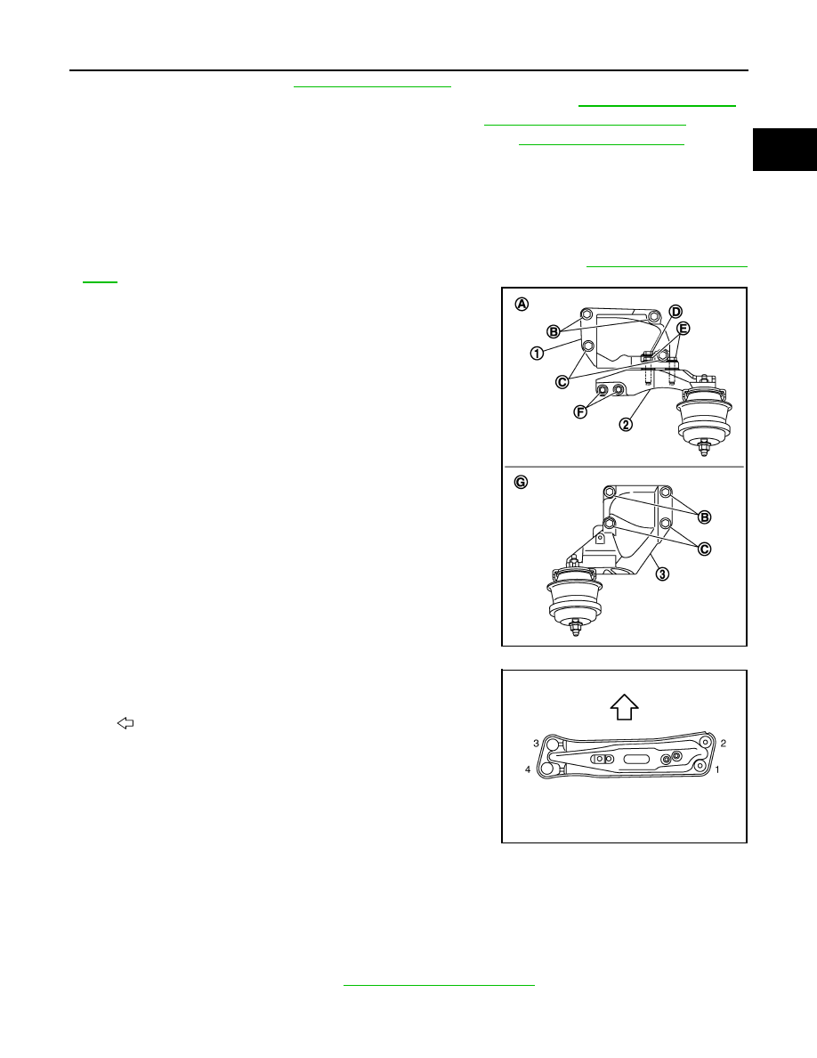
• When installing engine mounting bracket (RH and LH) on cylinder
block, tighten two upper bolts [shown as (B) in the figure] first.
Then tighten two lower bolts [shown as (C) in the figure].
• Install engine mounting bracket (RH) (lower) (2) as follows:
- Temporarily tighten mounting bolts [shown as (D), (E) and (F) in
the figure].
- Tighten mounting bolts to the specified torque with following
mounting surfaces touched.
• Engine mounting bracket (RH) (1) to engine mounting bracket
(RH) (lower) [shown as and in figure].
• Front final drive to engine mounting bracket (RH) (lower) [shown
as in figure].
• Check all engine mounting insulators are seated properly, then
tighten mounting nuts.
• Tighten rear engine mounting member bolts in numerical order as
shown in the figure.
AWD : Inspection
INFOID:0000000003139130
INSPECTION AFTER INSTALLATION
Inspection for Leakage
The following are procedures for checking fluids leakage, lubricates leakage and exhaust gases leakage.
• Before starting engine, check oil/fluid levels including engine coolant and engine oil. If less than required
quantity, fill to the specified level. Refer to
MA-10, "Fluids and Lubricants"
.
• Use procedure below to check for fuel leakage.
3
: Engine mounting bracket (LH)
A
: Right side
G : Left side
JPBIA0163ZZ
: Vehicle front
JPBIA0407ZZ
EM-88
< REMOVAL AND INSTALLATION >
ENGINE ASSEMBLY
- Turn ignition switch “ON” (with engine stopped). With fuel pressure applied to fuel piping, check for fuel leak-
age at connection points.
- Start engine. With engine speed increased, check again for fuel leakage at connection points.
• Run engine to check for unusual noise and vibration.
• Warm up engine thoroughly to check there is no leakage of fuel, exhaust gases, or any oil/fluids including
engine oil and engine coolant.
• Bleed air from lines and hoses of applicable lines, such as in cooling system.
• After cooling down engine, again check oil/fluid levels including engine oil and engine coolant. Refill to the
specified level, if necessary.
Summary of the inspection items:
*: Transmission/transaxle/CVT fluid, power steering fluid, brake fluid, etc.
Items
Before starting engine
Engine running
After engine stopped
Engine coolant
Level
Leakage
Level
Engine oil
Level
Leakage
Level
Other oils and fluid*
Level
Leakage
Level
Fuel
Leakage
Leakage
Leakage
Exhaust gases
—
Leakage
—
ENGINE STAND SETTING
EM-89
< DISASSEMBLY AND ASSEMBLY >
C
D
E
F
G
H
I
J
K
L
M
A
EM
N
P
O
DISASSEMBLY AND ASSEMBLY
ENGINE STAND SETTING
Setting
INFOID:0000000003139131
NOTE:
Explained here is how to disassemble with engine stand supporting transmission surface. When using differ-
ent type of engine stand, note with difference in steps and etc.
1.
Remove the engine assembly from the vehicle. Refer to
(2WD models) or
(AWD models).
2.
Remove the parts that may restrict installation of engine to widely use engine stand.
NOTE:
The procedure is described assuming that you use a widely use engine stand holding the surface, to
which transmission is installed.
• Remove drive plate with power tool. Fix crankshaft with a ring gear stopper [SST: KV10118600 (J-
48641)], and remove mounting bolts.
• Loosen mounting bolts in diagonal order.
• Check for deformation or damage drive plate.
CAUTION:
• Never disassemble drive plate.
• Never place drive plate with signal plate facing down.
• When handling signal plate, take care not to damage or scratch it.
• Handle signal plate in a manner that prevents it from becoming magnetized.
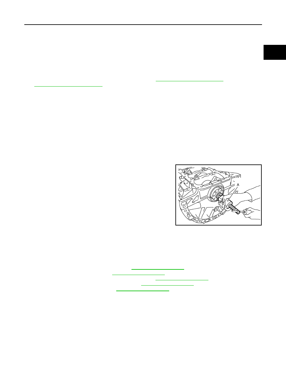
3.
Remove pilot converter using the pilot bushing puller [SST:
ST16610001 (J-23907)] (A) as necessary.
4.
Lift the engine with hoist to install it onto the widely use engine stand.
CAUTION:
Use an engine stand that has a load capacity [220 kg (485 lb) or more] large enough for supporting
the engine weight.
• If the load capacity of the stand is not adequate, remove the following parts beforehand to reduce the
potential risk of overturning the stand.
- Remove intake manifold collector. Refer to
.
- Remove intake manifold. Refer to
.
- Remove fuel injector and fuel tube assembly. Refer to
.
- Remove ignition coil and rocker cover. Refer to
.
- Remove exhaust manifold. Refer to
- Other removable brackets.
NOTE:
JPBIA0193ZZ
EM-90
< DISASSEMBLY AND ASSEMBLY >
ENGINE STAND SETTING
The figure shows an example of widely use engine stand (A)
that can hold mating surface of transmission with drive plate
removed.
CAUTION:
Before removing the hanging chains, check the engine
stand is stable and there is no risk of overturning.
5.
Drain engine oil. Refer to
.
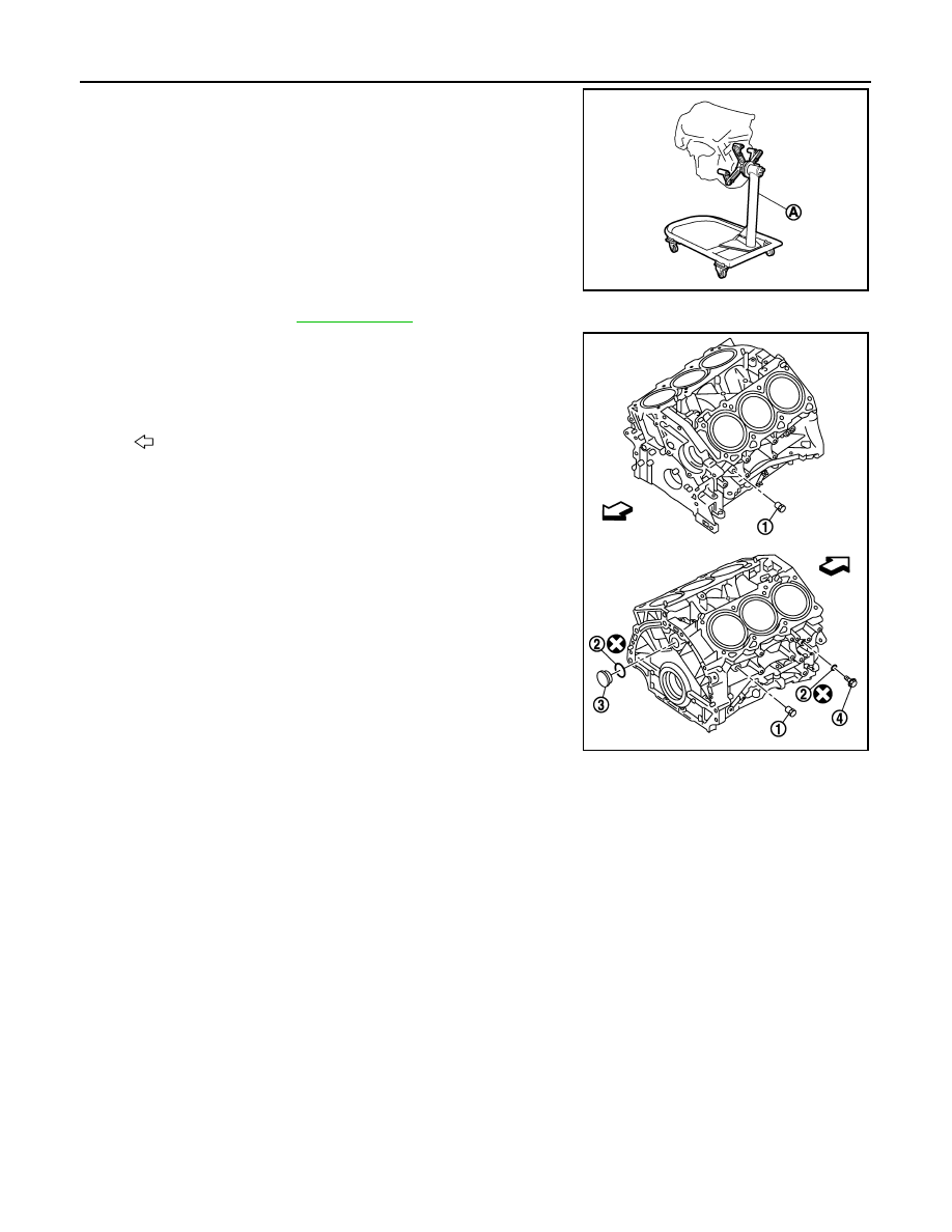
6.
Drain engine coolant by removing water drain plugs (1) and (4)
from cylinder block both sides as shown in the figure.
JPBIA0190ZZ
2
: Washer
3
: Plug
: Engine front
JPBIA0191ZZ
Нет комментариевНе стесняйтесь поделиться с нами вашим ценным мнением.
Текст