Infiniti EX35. Manual — part 723

ENGINE UNIT
EM-91
< DISASSEMBLY AND ASSEMBLY >
C
D
E
F
G
H
I
J
K
L
M
A
EM
N
P
O
ENGINE UNIT
Disassembly
INFOID:0000000003139132
1.
Remove intake manifold collector. Refer to
2.
Remove intake manifold. Refer to
3.
Remove exhaust manifold. Refer to
.
4.
Remove oil pan (lower). Refer to
(AWD models).
5.
Remove ignition coil, spark plug and rocker cover. Refer to
.
6.
Remove fuel injector and fuel tube. Refer to
7.
Remove timing chain. Refer to
.
8.
Remove rear timing chain case. Refer to
9.
Remove camshaft. Refer to
10. Remove cylinder head. Refer to
.
Assembly
INFOID:0000000003139133
Assembly in the reverse order of disassembly.
EM-92
< DISASSEMBLY AND ASSEMBLY >
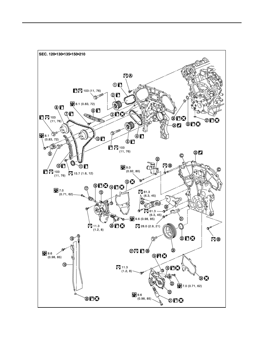
REAR TIMING CHAIN CASE
REAR TIMING CHAIN CASE
Exploded View
INFOID:0000000003567096
1.
Timing chain (secondary)
2.
Camshaft sprocket (EXH)
3.
O-ring
4.
Timing chain (secondary)
5.
Camshaft sprocket (EXH)
6.
Internal chain guide
7.
Timing chain (primary)
8.
Camshaft sprocket (INT)
9.
Timing chain tensioner (primary)
JPBIA1926GB

REAR TIMING CHAIN CASE
EM-93
< DISASSEMBLY AND ASSEMBLY >
C
D
E
F
G
H
I
J
K
L
M
A
EM
N
P
O
Disassembly
INFOID:0000000003139135
1.
Remove front timing chain case and timing chain. Refer to
.
2.
Remove water pump. Refer to
.
3.
Remove oil pan (upper). Refer to
(2WD models) or
(AWD models).
4.
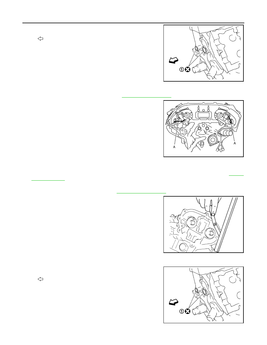
Remove rear timing chain case as follows:
a.
Loosen and remove mounting bolts in reverse order as shown in
the figure.
b.
Cut liquid gasket using the seal cutter [SST: KV10111100
(J37228)] and remove rear timing chain case.
CAUTION:
• Never remove plate metal cover (1) of oil passage.
• After removal, handle rear timing chain case carefully so
it does not tilt, cant, or warp under a load.
10. Slack guide
11. Crankshaft sprocket
12.
Camshaft sprocket (INT)
13.
Valve timing control cover gasket
(bank 1)
14. Seal ring
15.
Valve timing control cover (bank 1)
16. O-ring
17.
Exhaust valve timing control sole-
noid valve (bank 1)
18.
Oil level gauge
19. Oil level gauge guide
20. O-ring
21.
Intake valve timing control solenoid
valve (bank 2)
22. Valve timing control cover (bank 2)
23.
Exhaust valve timing control sole-
noid valve (bank 2)
24.
Valve timing control cover gasket (bank
2)
25. Front oil seal
26. Crankshaft pulley
27.
Crankshaft pulley bolt
28.
Intake valve timing control solenoid
valve (bank 1)
29. Power steering oil pump bracket
30.
Idler pulley bracket
31. Alternator bracket
32. Water outlet (front)
33.
Front timing chain case
34. Rear timing chain case
35. O-ring
36.
O-ring
37. O-ring
A.
Refer to
B.
C.
Oil filter
Refer to
for symbols in the figure.
JPBIA0089ZZ
JPBIA0088ZZ
EM-94
< DISASSEMBLY AND ASSEMBLY >
REAR TIMING CHAIN CASE
5.
Remove O-rings (1) from cylinder block.
6.
Remove timing chain tensioners (secondary) from cylinder head as follows, if necessary.
a.
Remove camshaft brackets (No. 1). Refer to
b.
Remove timing chain tensioners (secondary) with a stopper pin
(A) attached.
Assembly
INFOID:0000000003139136
1.
Install timing chain tensioners (secondary) to cylinder head as follows if removed. Refer to
a.
Install timing chain tensioners (secondary) with a stopper pin attached and new O-rings.
b.
Install camshaft brackets (No. 1). Refer to
.
c.
Measure difference in levels between front end faces of cam-
shaft bracket (No. 1) and cylinder head.
• Measure two positions (both intake and exhaust side) for a
single bank.
• If the measured value is out of the standard, re-install cam-
shaft bracket (No. 1).
2.
Install rear timing chain case as follows:
a.
Install new O-rings (1) onto cylinder block.
: Engine front
JPBIA0090ZZ
JPBIA0095ZZ
Standard
:
−
0.14 to 0.14 mm (
−
0.0055 to 0.0055 in)
EMQ0044D
: Engine front
JPBIA0090ZZ
Нет комментариевНе стесняйтесь поделиться с нами вашим ценным мнением.
Текст