Infiniti EX35. Manual — part 1487
WCS
DIAGNOSIS AND REPAIR WORKFLOW
WCS-3
< BASIC INSPECTION >
C
D
E
F
G
H
I
J
K
L
M
B
A
O
P
BASIC INSPECTION
DIAGNOSIS AND REPAIR WORKFLOW
Work Flow
INFOID:0000000003135078
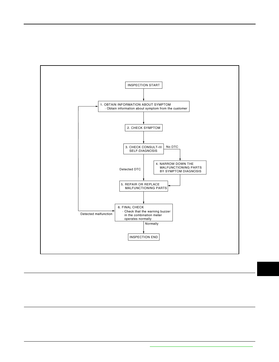
OVERALL SEQUENCE
DETAILED FLOW
1.
OBTAIN INFORMATION ABOUT SYMPTOM
Interview the customer to obtain as much information as possible about the conditions and environment under
which the malfunction occurred.
>> GO TO 2.
2.
CHECK SYMPTOM
• Check the symptom based on the information obtained from the customer.
• Check that any other malfunctions are present.
>> GO TO 3.
3.
CHECK CONSULT-III SELF-DIAGNOSIS RESULTS
Connect CONSULT-III and perform self-diagnosis. Refer to
MWI-40, "CONSULT-III Function (METER/M&A)"
.
JSNIA0456GB

WCS-4
< BASIC INSPECTION >
DIAGNOSIS AND REPAIR WORKFLOW
Are self-diagnosis results normal?
YES
>> GO TO 4.
NO
>> GO TO 5.
4.
NARROW DOWN MALFUNCTIONING PARTS BY SYMPTOM DIAGNOSIS
Perform symptom diagnosis and narrow down the malfunctioning parts.
>> GO TO 5.
5.
REPAIR OR REPLACE MALFUNCTIONING PARTS
Repair or replace malfunctioning parts.
NOTE:
If DTC is displayed, erase DTC after repair or replace malfunctioning parts.
>> GO TO 6.
6.
FINAL CHECK
Check that the warning buzzer in the combination meter operates normally.
Does it operate normally?
YES
>> INSPECTION END
NO
>> GO TO 1.
WCS
WARNING CHIME SYSTEM
WCS-5
< FUNCTION DIAGNOSIS >
C
D
E
F
G
H
I
J
K
L
M
B
A
O
P
FUNCTION DIAGNOSIS
WARNING CHIME SYSTEM
WARNING CHIME SYSTEM
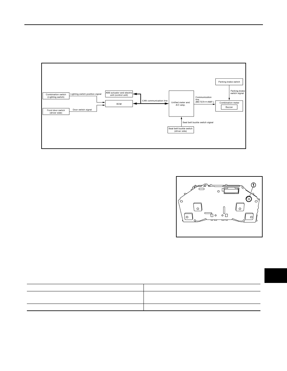
WARNING CHIME SYSTEM : System Diagram
INFOID:0000000003135079
WARNING CHIME SYSTEM : System Description
INFOID:0000000003135080
COMBINATION METER
• The buzzer (1) for warning chime system is installed in the combi-
nation meter.
• The buzzer sounds when the combination meter receives buzzer
output signal from each unit through unified meter and A/C amp.
UNIFIED METER AND A/C AMP.
The unified meter and A/C amp. transmits the buzzer output signal received from BCM with CAN communica-
tion line to the combination meter.
BCM
BCM receives signals from various units and transmits a buzzer output signal to the unified meter and A/C
amp. with CAN communication line if it judges that the warning buzzer should be activated.
BCM warning function list
JSNIA0500GB
JPNIA0764ZZ
Warning functions
Signal name
Light reminder warning chime
• Lighting switch position signal
• Door switch signal
Seat belt warning chime
Seat belt buckle switch signal

WCS-6
< FUNCTION DIAGNOSIS >
WARNING CHIME SYSTEM
WARNING CHIME SYSTEM : Component Parts Location
INFOID:0000000003135081
WARNING CHIME SYSTEM : Component Description
INFOID:0000000003135082
1.
BCM
2.
ABS actuator and electric unit (con-
trol unit)
3.
Unified meter and A/C amp.
4.
Front door switch (driver side)
5.
Combination switch
(Lighting switch)
6.
Parking brake switch
7.
Seat belt buckle switch (driver side)
8.
Combination meter
A.
Dash side lower (passenger side)
B.
Hoodledge cover (LH)
C.
Behind cluster lid C
JPNIA0869ZZ
Unit
Description
Combination meter
• Receives a buzzer output signal from the unified meter and A/C amp. and sounds the buzzer.
• Judges whether the parking brake is released from the vehicle speed signal received from the
unified meter and A/C amp. with CAN communication line and the parking brake switch signal
from the parking brake switch, and sounds the buzzer if necessary.
Unified meter and A/C amp.
• Receives the seat belt buckle switch signal from the seat belt buckle switch and transmits it to
BCM with CAN communication line.
• Receives a buzzer output signal from BCM with CAN communication line and transmits it to
the combination meter by means of communication line.
BCM
Transmits signals provided by various units to the unified meter and A/C amp. with CAN com-
munication line.
ABS actuator and electric unit
(control unit)
Transmits the vehicle speed signal to BCM with CAN communication line.
Seat belt buckle switch (driver
side)
Transmits a seat belt buckle switch signal to the unified meter and A/C amp.
Нет комментариевНе стесняйтесь поделиться с нами вашим ценным мнением.
Текст