Infiniti EX35. Manual — part 1480
VTL-38
< ON-VEHICLE REPAIR >
HEATER & COOLING UNIT ASSEMBLY
Removal and Installation
INFOID:0000000003545417
REMOVAL
1.
Use a refrigerant collecting equipment (for HFC-134a) to discharge the refrigerant.
2.
Drain engine coolant from cooling system. Refer to
3.
Remove cowl top cover. Refer to
.
4.
Remove engine cover. Refer to
5.
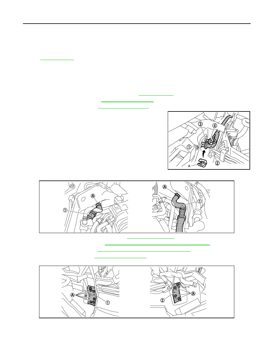
Disconnect one-touch joint between low-pressure pipe 1 (1) and
low-pressure pipe 2 (2) with disconnector (SST: 9253089916)
(A).
CAUTION:
Cap or wrap the joint of the A/C piping with suitable mate-
rial such as vinyl tape to avoid the entry of air.
6.
Disconnect one-touch joint between high-pressure pipe 1 (4)
and high-pressure pipe 2 (3) with disconnector (SST:
9253089908).
CAUTION:
Cap or wrap the joint of the A/C piping with suitable mate-
rial such as vinyl tape to avoid the entry of air.
7.
Remove clamps (A), and then disconnect heater hoses (1).
8.
Remove instrument panel assembly. Refer to
9.
Remove defroster nozzle. Refer to
VTL-52, "DEFROSTER NOZZLE : Exploded View"
10. Remove adaptor duct. Refer to
VTL-51, "ADAPTOR DUCT : Exploded View"
.
11. Remove blower unit. Refer to
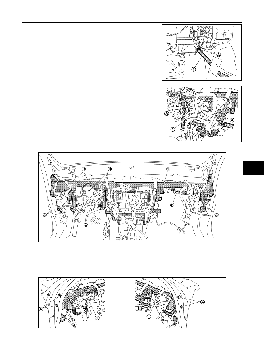
12. Remove mounting nuts (A), and then remove instrument stay (left) (1) and instrument stay (right) (2).
49. Max. cool door lever
50.
Defroster door lever
51.
Defroster door link
52. Max. cool door link
53.
Intake sensor
54.
Intake sensor bracket
55. Air mix door motor (passenger side)
56.
Air mix door adapter
57.
Heater & cooling unit case (right)
58. Max. cool door (right)
59.
Max. cool door (left)
60.
Air mix door (Slide door)
*With left and right ventilation temperature separately system.
for symbols in the figure.
JPIIA0657ZZ
JPIIA0658ZZ
JPIIA0659ZZ
HEATER & COOLING UNIT ASSEMBLY
VTL-39
< ON-VEHICLE REPAIR >
C
D
E
F
G
H
J
K
L
M
A
B
VTL
N
O
P
13. Remove clamp (A), and then disconnect drain hose (1).
14. Remove mounting bolts (A) from steering member (1).
15. Remove mounting bolts (A) from steering member (1).
16. Remove ground bolts (B) from steering member.
17. Remove steering column mounting nuts (C) and bolts (D). Refer to
(WITHOUT ELECTRIC MOTOR) or
(WITH ELECTRIC MOTOR).
18. Remove harness connector and clips of vehicle harness from steering member.
19. Remove mounting bolts (A) from steering member (1).
JPIIA0660ZZ
JPIIA0661ZZ
JPIIA0662ZZ
JPIIA0663ZZ
VTL-40
< ON-VEHICLE REPAIR >
HEATER & COOLING UNIT ASSEMBLY
20. Remove steering member, and then remove heater & cooling unit assembly.
INSTALLATION
Installation is basically the reverse order of removal.
CAUTION:
• Replace O-rings with new ones. Then apply compressor oil to them when installing.
• Female-side piping connection is thin and easy to deform. Slowly insert the male-side piping
straight in axial direction.
• Insert piping securely until a clicks is heard.
• After piping connection is completed, pull male-side piping by hand to make sure that connection
does not come loose.
• Check for leakages when recharging refrigerant.
NOTE:
• Refer to
when filling radiator with engine coolant.
• Recharge the refrigerant.
MODE DOOR MOTOR
VTL-41
< ON-VEHICLE REPAIR >
C
D
E
F
G
H
J
K
L
M
A
B
VTL
N
O
P
MODE DOOR MOTOR
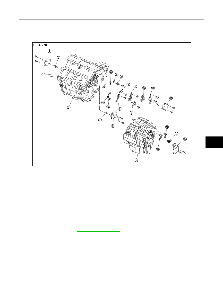
Exploded View
INFOID:0000000003567023
Removal and Installation
INFOID:0000000003545419
REMOVAL
1.
Remove blower unit. Refer to
1.
Air mix door motor (driver side)
2.
Air mix door motor adapter
3.
Heater & cooling unit assembly
4.
Ventilator door lever
5.
Foot door lever
6.
Foot door link
7.
Air mix door motor adapter
8.
Air mix door motor (passenger side) 9.
Ventilator door link
10. Blower unit
11.
Intake door lever 2
12. Intake door motor
13. Intake door link
14.
Intake door lever 1
15. Mode door motor
16. Mode door motor bracket
17.
Main link
18. Main link sub
19. Max.cool door link
20.
Defroster door link
21. Max.cool door lever
22. Defroster door lever
JPIIA0654ZZ
Нет комментариевНе стесняйтесь поделиться с нами вашим ценным мнением.
Текст