Infiniti EX35. Manual — part 394
CCS
ACTION TEST
CCS-111
< BASIC INSPECTION >
[LDW & LDP]
C
D
E
F
G
H
I
J
K
L
M
B
N
P
A
>> WORK END
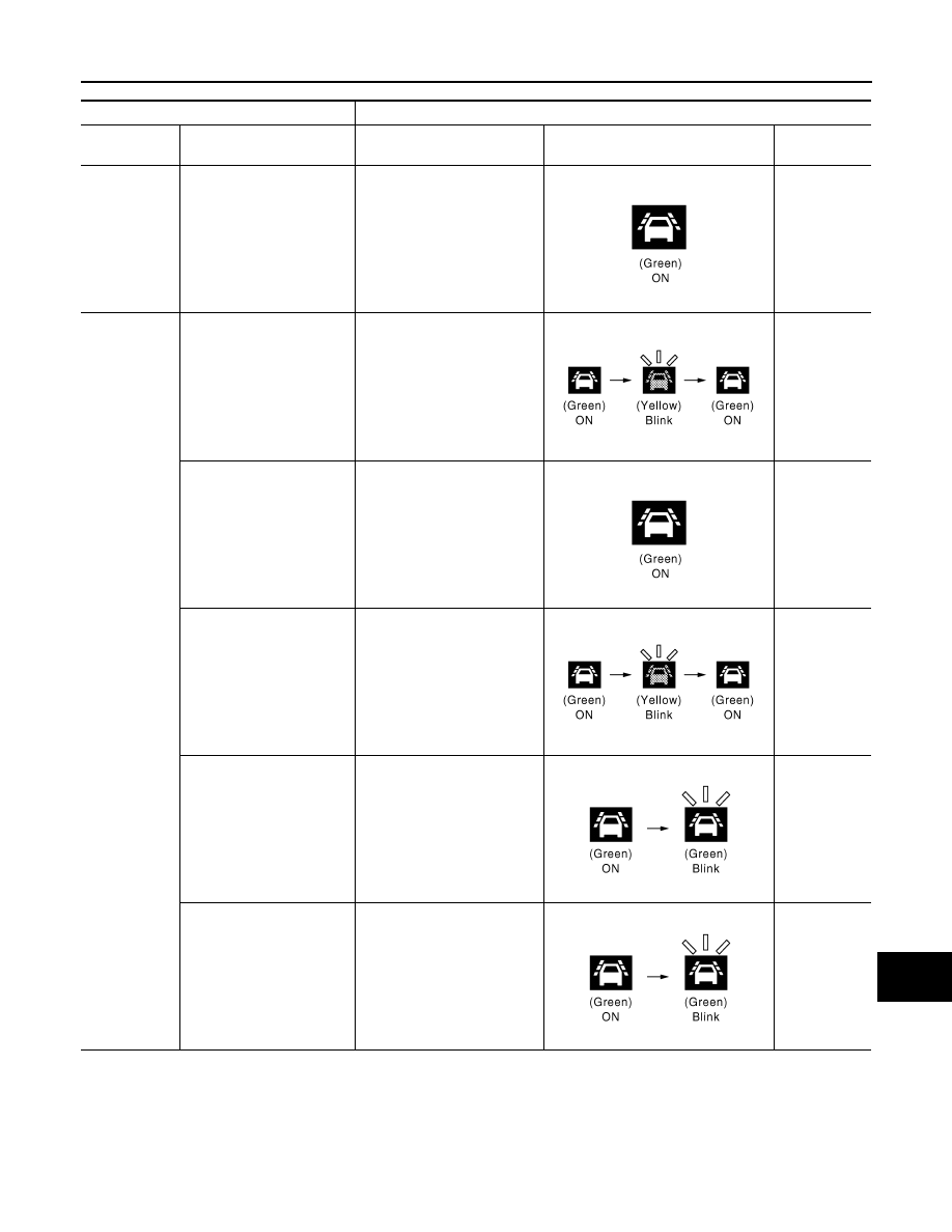
Input
Output
Vehicle speed
[Km/h (MPH)]
Vehicle condition/ Driver's
operation
Action
Indication on the combination meter
Buzzer
Less than 64
(40)
Close to lane marker
No action
—
72 (45) or
more
Close to lane marker
Warning and yawing
• Buzzer sounds
• Warning lamp blinks
• Brake control
Short continu-
ous beeps
• Close to lane marker
• Turn signal ON (Deviate
side)
No action
—
Close to lane marker with
soft braking
Warning
• Buzzer sounds
• Warning lamp blinks
Short continu-
ous beeps
VDC OFF switch:
OFF
⇒
ON
Cancellation
• Buzzer sounds
• Indicator lamp blinks
NOTE:
When LDP ON switch is ON
⇒
OFF, indicator lamp is turned
OFF.
Beep
Snow mode switch:
OFF
⇒
ON
(If equipped)
Cancellation
• Buzzer sounds
• Indicator lamp blinks
NOTE:
When LDP ON switch is ON
⇒
OFF, indicator lamp is turned
OFF.
Beep
JPOIA0021GB
JPOIA0022GB
JPOIA0021GB
JPOIA0022GB
JPOIA0023GB
JPOIA0023GB

CCS-112
< BASIC INSPECTION >
[LDW & LDP]
INSPECTION AND ADJUSTMENT
INSPECTION AND ADJUSTMENT
ADDITIONAL SERVICE WHEN REPLACING CONTROL UNIT (LANE CAMERA
UNIT)
ADDITIONAL SERVICE WHEN REPLACING CONTROL UNIT (LANE CAMERA
UNIT) : Description
INFOID:0000000003514561
Always perform the camera aiming adjustment after replacing the lane camera unit.
ADDITIONAL SERVICE WHEN REPLACING CONTROL UNIT (LANE CAMERA
UNIT) : Special Repair Requirement
INFOID:0000000003514562
1.
CAMERA AIMING ADJUSTMENT
Perform the camera aiming adjustment with CONSULT-III. Refer to
CCS-112, "CAMERA AIMING ADJUST-
>> GO TO 2.
2.
PERFORM SELF-DIAGNOSIS
Perform the self-diagnosis of lane camera unit with CONSULT-III. Check if any DTC is detected.
Is any DTC detected?
YES
>> Perform the trouble diagnosis for the detected DTC. Refer to
NO
>> GO TO 3.
3.
LDW/LDP SYSTEM ACTION TEST
1.
Perform the LDW/LDP system action test. Refer to
2.
Check that the LDW/LDP system operates normally.
>> WORK END
CAMERA AIMING ADJUSTMENT
CAMERA AIMING ADJUSTMENT : Description
INFOID:0000000003514563
OUTLINE
Perform the camera aiming every time the lane camera unit is removed and installed.
CAUTION:
• Place the vehicle on level ground when the camera aiming adjustment is operated.
• Follow the CONSULT-III when performing the camera aiming. (Camera aiming adjustment cannot be
operated without CONSULT-III.)
CAMERA AIMING ADJUSTMENT : Special Repair Requirement (Preparation)
INFOID:0000000003514564
1.
PERFORM SELF-DIAGNOSIS
Perform self-diagnosis of lane camera unit.
Is any DTC detected?
Except “C1B01”>>Perform diagnosis on the detected DTC and repair or replace the applicable item. Refer to
“C1B01” or no DTC>>GO TO 2.
2.
PREPARATION BEFORE CAMERA AIMING ADJUSTMENT
1.
Adjust the tire pressure to the specified pressure value.
2.
Maintain no-load in vehicle.
3.
Check if coolant and Engine oil are filled up to correct level and fuel tank is full.
4.
Shift the selector lever to “P” position and release the parking brake.
5.
Clean the windshield.
CCS
INSPECTION AND ADJUSTMENT
CCS-113
< BASIC INSPECTION >
[LDW & LDP]
C
D
E
F
G
H
I
J
K
L
M
B
N
P
A
6.
Completely clear off the instrument panel.
>> GO TO 3.
3.
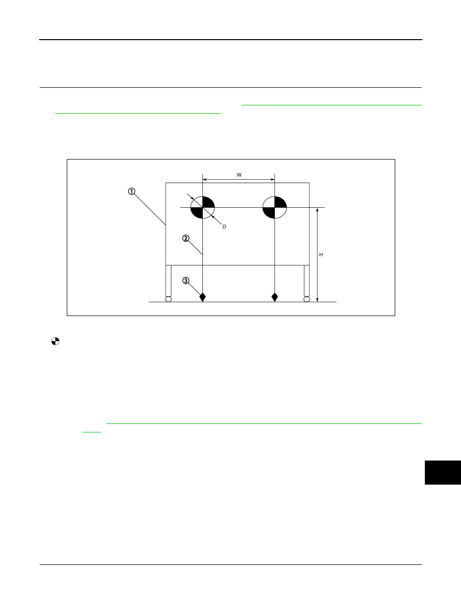
PREPARATION OF AIMING ADJUSTMENT JIG
Prepare the aiming adjustment jig according to the following procedure and the figure.
1.
Print out the target mark attached in this SM. Refer to
CCS-116, "CAMERA AIMING ADJUSTMENT : Spe-
cial Repair Requirement (Target Mark Sample)"
.
2.
Stick a printed target mark on the board with a scotch tape or a piece of double-sided tape.
NOTE:
• Use the board that peripheral area of the target is monochrome such as a white-board.
• Notice that the cross of the target is horizontal and vertical.
>> Go to
CCS-113, "CAMERA AIMING ADJUSTMENT : Special Repair Requirement (Target Set-
.
CAMERA AIMING ADJUSTMENT : Special Repair Requirement (Target Setting)
INFOID:0000000003514565
CAUTION:
• Perform this operation in a horizontal position where there is a clear view for 5 m (16.4 ft) forward
and 3 m (9.84 ft) wide.
• Place the target in a well-lighted location. (Poor lighting may make it hard to adjust.)
• The target may not be detected when there is a light source within 1.5 m (4.92 ft) from either side and
within 1 m (3.28 ft) upward/downward from the target.
• Check the location of the sun. (Sunlight should not shine directly on the front of the vehicle.)
• The target may not be detected when there is the same pattern of black and white as the target when
the pattern is within 1 m (3.28 ft) from either side and upward/downward position from the target. (It
is desirable that the vehicle is positioned on the opposite side of a single-color wall.)
1.
TARGET SETTING
1.
Board
2.
String
3.
Cone
: Target mark
Diameter of a target (D)
: 200 mm (7.87 in)
Height of a target center (H)
: 1450 mm (57.09 in)
Width between a right target cen-
ter from a left target center (W)
: 600 mm (23.62 in)
JPOIA0011ZZ
CCS-114
< BASIC INSPECTION >
[LDW & LDP]
INSPECTION AND ADJUSTMENT
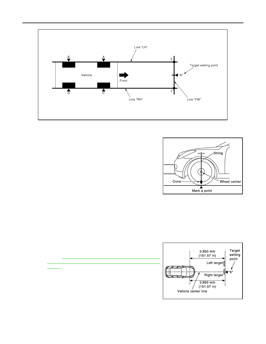
1.
Mark points “A”, “B”, “C” and “D”at the center of the lateral sur-
face of each wheels.
NOTE:
Hang a string with a cone from the fender so as to pass through
the center of wheel, and then mark a point at the center of the
lateral surface of the wheel.
2.
Draw line “LH” passing through points “A” and “B” on the left side
of vehicle.
NOTE:
Approximately 4 m (13.12 ft) or more from the front end of vehi-
cle.
3.
Mark point “E” on the line “LH” at the positions 3850 mm (151.57
in) from point “A”.
4.
Draw line “RH” passing through points “C” and “D” on the right side of vehicle in the same way as step 2.
NOTE:
Approximately 4 m (13.12 ft) or more from the front end of vehicle.
5.
Mark point “FW” on the line “RH” at the positions 3850 mm (151.57 in) from point “C”.
6.
Draw line “E” and “F” passing through the points.
7.
Mark point “X” at the center of point “E” and “F” on the line “FW”.
CAUTION:
Make sure that “E” to “X” is equal to “F” to “X”.
8.
Position the center of the right target to point of “X”.
>> Go to
CCS-114, "CAMERA AIMING ADJUSTMENT :
Special Repair Requirement (Camera Aiming Adjust-
ment)"
CAMERA AIMING ADJUSTMENT : Special Repair Requirement (Camera Aiming Ad-
justment)
INFOID:0000000003514566
CAUTION:
Perform the adjustment under unloaded vehicle condition.
“A” – “E” (“C” – “F”)
: 3850 mm (151.57 in)
PKIB4694E
JPMIA0930GB
JPMIA0931GB
Нет комментариевНе стесняйтесь поделиться с нами вашим ценным мнением.
Текст