Infiniti EX35. Manual — part 606
EC-166
< COMPONENT DIAGNOSIS >
[VQ35HR]
P0102, P0103, P010C, P010D MAF SENSOR
2.
Disconnect ECM harness connector.
3.
Check the continuity between MAF sensor harness connector and ECM harness connector.
4.
Also check harness for short to ground and short to power.
Is the inspection result normal?
YES
>> GO TO 7.
NO
>> Repair open circuit or short to ground or short to power in harness or connectors.
7.
CHECK MAF SENSOR INPUT SIGNAL CIRCUIT FOR OPEN AND SHORT
1.
Check the continuity between MAF sensor harness connector and ECM harness connector.
2.
Also check harness for short to ground and short to power.
Is the inspection result normal?
YES
>> GO TO 8.
NO
>> Repair open circuit or short to ground or short to power in harness or connectors.
8.
CHECK MASS AIR FLOW SENSOR
EC-166, "Component Inspection"
Is the inspection result normal?
YES
>> GO TO 9.
NO
>> Replace malfunctioning mass air flow sensor.
9.
CHECK INTERMITTENT INCIDENT
GI-38, "Intermittent Incident"
>> INSPECTION END
Component Inspection
INFOID:0000000003133327
1.
CHECK MASS AIR FLOW SENSOR-I
With CONSULT-III
1.
Turn ignition switch OFF.
2.
Reconnect all harness connectors disconnected.
3.
Start engine and warm it up to normal operating temperature.
4.
Connect CONSULT-III and select “DATA MONITOR” mode.
5.
Select “MAS A/F SE-B1” and “MAS A/F SE-B2”, and check the indication.
*: Check for linear voltage rise in response to engine being increased to about 4,000 rpm.
Without CONSULT-III
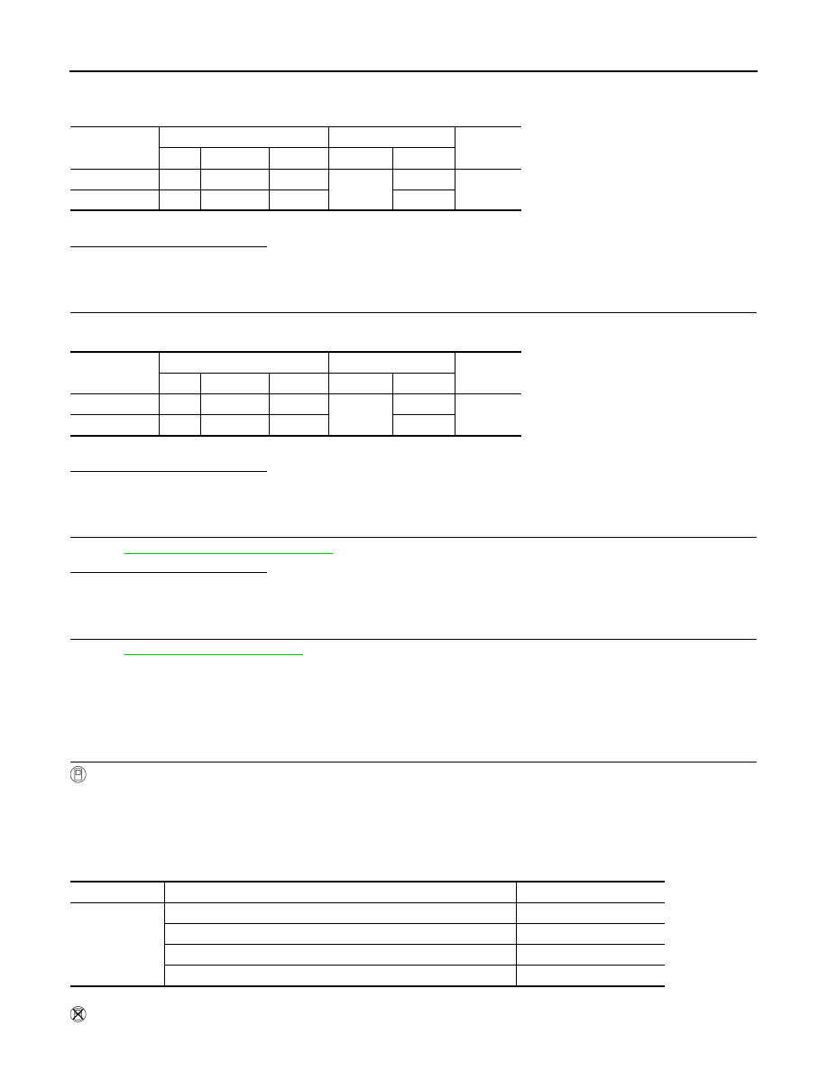
DTC
MAF sensor
ECM
Continuity
Bank
Connector
Terminal
Connector
Terminal
P0102, P0103
1
F31
4
F102
68
Existed
P010C, P010D
2
F42
4
94
DTC
MAF sensor
ECM
Continuity
Bank
Connector
Terminal
Connector
Terminal
P0102, P0103
1
F31
3
F102
77
Existed
P010C, P010D
2
F42
3
79
Monitor item
Condition
Indication (V)
MAS A/F SE-B1
MAS A/F SE-B2
Ignition switch ON (Engine stopped.)
Approx. 0.4
Idle (Engine is warmed-up to normal operating temperature.)
0.8 - 1.1
2,500 rpm (Engine is warmed-up to normal operating temperature.)
1.4 - 1.7
Idle to about 4,000 rpm
0.8 - 1.1 to Approx. 2.4*
P0102, P0103, P010C, P010D MAF SENSOR
EC-167
< COMPONENT DIAGNOSIS >
[VQ35HR]
C
D
E
F
G
H
I
J
K
L
M
A
EC
N
P
O
1.
Turn ignition switch OFF.
2.
Reconnect all harness connectors disconnected.
3.
Start engine and warm it up to normal operating temperature.
4.
Check the voltage between ECM harness connector terminals under the following conditions.
*: Check for linear voltage rise in response to engine being increased to about 4,000 rpm.
Is the inspection result normal?
YES
>> GO TO 4.
NO
>> GO TO 2.
2.
CHECK FOR THE CAUSE OF UNEVEN AIR FLOW THROUGH MASS AIR FLOW SENSOR
1.
Turn ignition switch OFF.
2.
Check for the cause of uneven air flow through mass air flow sensor. Refer to the following.
-
Crushed air ducts
-
Malfunctioning seal of air cleaner element
-
Uneven dirt of air cleaner element
-
Improper specification of intake air system parts
Is the inspection result normal?
YES
>> GO TO 4.
NO
>> GO TO 3.
3.
CHECK MASS AIR FLOW SENSOR-II
With CONSULT-III
1.
Repair or replace malfunctioning part.
2.
Start engine and warm it up to normal operating temperature.
3.
Connect CONSULT-III and select “DATA MONITOR” mode.
4.
Select “MAS A/F SE-B1” and “MAS A/F SE-B2”, and check the indication.
*: Check for linear voltage rise in response to engine being increased to about 4,000 rpm.
Without CONSULT-III
1.
Repair or replace malfunctioning part.
2.
Start engine and warm it up to normal operating temperature.
3.
Check the voltage between ECM harness connector terminals under the following conditions.
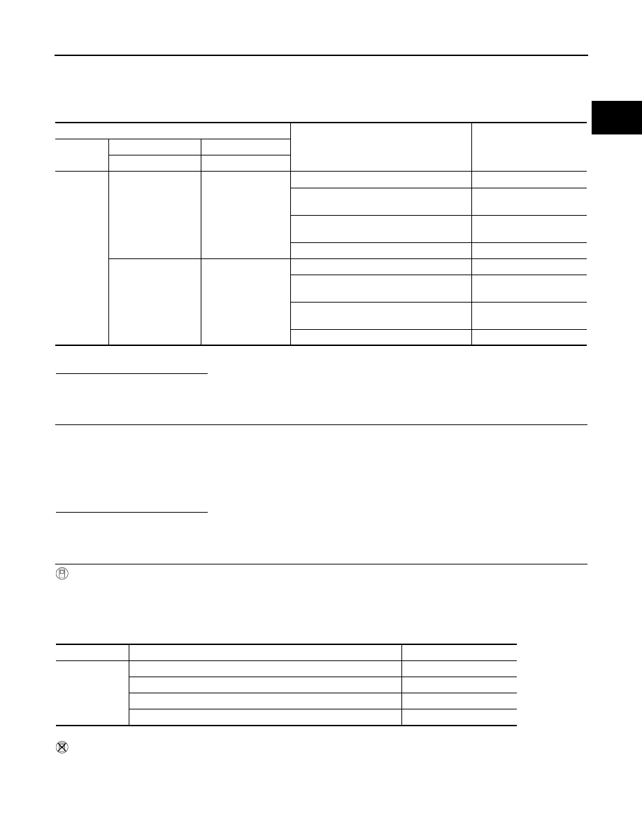
ECM
Condition
Voltage (V)
Connector
+
–
Terminal
Terminal
F102
77
[MAF sensor (bank 1)
signal]
68
Ignition switch ON (Engine stopped.)
Approx. 0.4
Idle (Engine is warmed-up to normal operat-
ing temperature.)
0.8 - 1.1
2,500 rpm (Engine is warmed-up to normal
operating temperature.)
1.4 - 1.7
Idle to about 4,000 rpm
0.8 - 1.1 to Approx. 2.4*
79
[MAF sensor (bank 2)
signal]
94
Ignition switch ON (Engine stopped.)
Approx. 0.4
Idle (Engine is warmed-up to normal operat-
ing temperature.)
0.8 - 1.1
2,500 rpm (Engine is warmed-up to normal
operating temperature.)
1.4 - 1.7
Idle to about 4,000 rpm
0.8 - 1.1 to Approx. 2.4*
Monitor item
Condition
Indication (V)
MAS A/F SE-B1
MAS A/F SE-B2
Ignition switch ON (Engine stopped.)
Approx. 0.4
Idle (Engine is warmed-up to normal operating temperature.)
0.8 - 1.1
2,500 rpm (Engine is warmed-up to normal operating temperature.)
1.4 - 1.7
Idle to about 4,000 rpm
0.8 - 1.1 to Approx. 2.4*
EC-168
< COMPONENT DIAGNOSIS >
[VQ35HR]
P0102, P0103, P010C, P010D MAF SENSOR
*: Check for linear voltage rise in response to engine being increased to about 4,000 rpm.
Is the inspection result normal?
YES
>> INSPECTION END
NO
>> GO TO 4.
4.
CHECK MASS AIR FLOW SENSOR-III
With CONSULT-III
1.
Turn ignition switch OFF.
2.
Disconnect mass air flow sensor harness connector and reconnect it again.
3.
Start engine and warm it up to normal operating temperature.
4.
Connect CONSULT-III and select “DATA MONITOR” mode.
5.
Select “MAS A/F SE-B1” and “MAS A/F SE-B2”, and check the indication.
*: Check for linear voltage rise in response to engine being increased to about 4,000 rpm.
Without CONSULT-III
1.
Turn ignition switch OFF.
2.
Disconnect mass air flow sensor harness connector and reconnect it again.
3.
Start engine and warm it up to normal operating temperature.
4.
Check the voltage between ECM harness connector terminals under the following conditions.
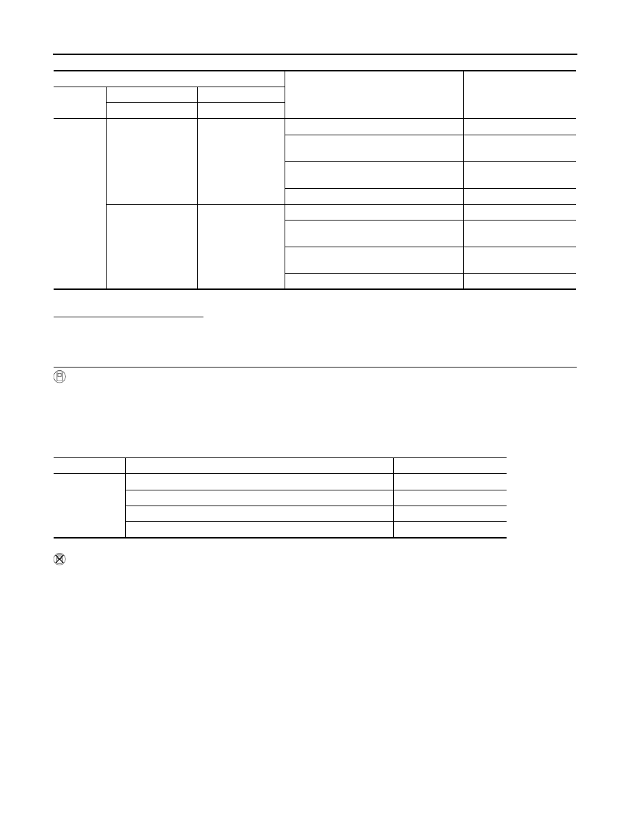
ECM
Condition
Voltage (V)
Connector
+
–
Terminal
Terminal
F102
77
[MAF sensor (bank 1)
signal]
68
Ignition switch ON (Engine stopped.)
Approx. 0.4
Idle (Engine is warmed-up to normal operat-
ing temperature.)
0.8 - 1.1
2,500 rpm (Engine is warmed-up to normal
operating temperature.)
1.4 - 1.7
Idle to about 4,000 rpm
0.8 - 1.1 to Approx. 2.4*
79
[MAF sensor (bank 2)
signal]
94
Ignition switch ON (Engine stopped.)
Approx. 0.4
Idle (Engine is warmed-up to normal operat-
ing temperature.)
0.8 - 1.1
2,500 rpm (Engine is warmed-up to normal
operating temperature.)
1.4 - 1.7
Idle to about 4,000 rpm
0.8 - 1.1 to Approx. 2.4*
Monitor item
Condition
Indication (V)
MAS A/F SE-B1
MAS A/F SE-B2
Ignition switch ON (Engine stopped.)
Approx. 0.4
Idle (Engine is warmed-up to normal operating temperature.)
0.8 - 1.1
2,500 rpm (Engine is warmed-up to normal operating temperature.)
1.4 - 1.7
Idle to about 4,000 rpm
0.8 - 1.1 to Approx. 2.4*
P0102, P0103, P010C, P010D MAF SENSOR
EC-169
< COMPONENT DIAGNOSIS >
[VQ35HR]
C
D
E
F
G
H
I
J
K
L
M
A
EC
N
P
O
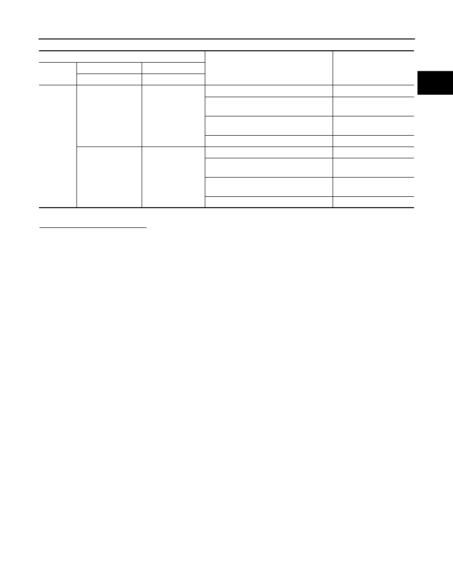
*: Check for linear voltage rise in response to engine being increased to about 4,000 rpm.
Is the inspection result normal?
YES
>> INSPECTION END
NO
>> Clean or replace malfunctioning mass air flow sensor.
ECM
Condition
Voltage (V)
Connector
+
–
Terminal
Terminal
F102
77
[MAF sensor (bank 1)
signal]
68
Ignition switch ON (Engine stopped.)
Approx. 0.4
Idle (Engine is warmed-up to normal operat-
ing temperature.)
0.8 - 1.1
2,500 rpm (Engine is warmed-up to normal
operating temperature.)
1.4 - 1.7
Idle to about 4,000 rpm
0.8 - 1.1 to Approx. 2.4*
79
[MAF sensor (bank 2)
signal]
94
Ignition switch ON (Engine stopped.)
Approx. 0.4
Idle (Engine is warmed-up to normal operat-
ing temperature.)
0.8 - 1.1
2,500 rpm (Engine is warmed-up to normal
operating temperature.)
1.4 - 1.7
Idle to about 4,000 rpm
0.8 - 1.1 to Approx. 2.4*
Нет комментариевНе стесняйтесь поделиться с нами вашим ценным мнением.
Текст