Infiniti EX35. Manual — part 607
EC-170
< COMPONENT DIAGNOSIS >
[VQ35HR]
P0112, P0113 IAT SENSOR
P0112, P0113 IAT SENSOR
Description
INFOID:0000000003133328
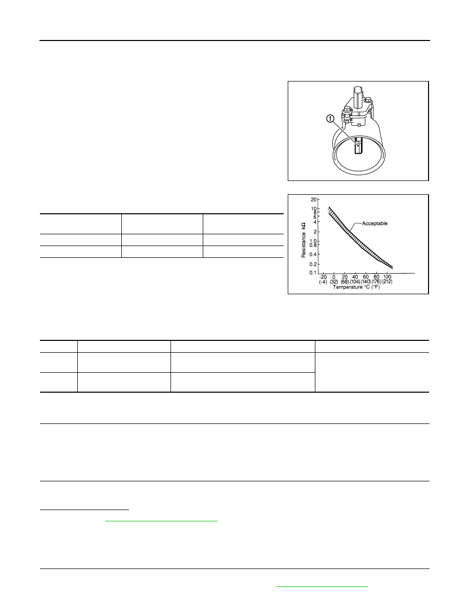
The intake air temperature sensor is built-into mass air flow sensor
(1). The sensor detects intake air temperature and transmits a signal
to the ECM.
The temperature sensing unit uses a thermistor which is sensitive to
the change in temperature. Electrical resistance of the thermistor
decreases in response to the temperature rise.
NOTE:
ECM uses only the intake air temperature sensor (bank 1) for engine
control and self-diagnosis. It does not use the intake air temperature
sensor (bank 2).
<Reference data>
*: These data are reference values and are measured between ECM terminals 67
(Intake air temperature sensor) and 68 (Sensor ground).
DTC Logic
INFOID:0000000003133329
DTC DETECTION LOGIC
DTC CONFIRMATION PROCEDURE
1.
PRECONDITIONING
If DTC Confirmation Procedure has been previously conducted, always turn ignition switch OFF and wait at
least 10 seconds before conducting the next test.
>> GO TO 2.
2.
PERFORM DTC CONFIRMATION PROCEDURE
1.
Turn ignition switch ON and wait at least 5 seconds.
2.
Check 1st trip DTC.
Is 1st trip DTC detected?
YES
>> Go to
NO
>> INSPECTION END
Diagnosis Procedure
INFOID:0000000003133330
1.
CHECK GROUND CONNECTION
1.
Turn ignition switch OFF.
2.
Check ground connection M95. Refer to Ground Inspection in
PBIA9559J
Intake air temperature
[
°
C (
°
F)]
Voltage*
(V)
Resistance
(k
Ω
)
25 (77)
3.3
1.800 - 2.200
80 (176)
1.2
0.283 - 0.359
SEF012P
DTC No.
Trouble diagnosis name
DTC detecting condition
Possible cause
P0112
Intake air temperature sensor
(bank 1) circuit low input
An excessively low voltage from the sensor is
sent to ECM.
• Harness or connectors
(The sensor circuit is open or short-
ed.)
• Intake air temperature sensor
P0113
Intake air temperature sensor
(bank 1) circuit high input
An excessively high voltage from the sensor is
sent to ECM.

P0112, P0113 IAT SENSOR
EC-171
< COMPONENT DIAGNOSIS >
[VQ35HR]
C
D
E
F
G
H
I
J
K
L
M
A
EC
N
P
O
Is the inspection result normal?
YES
>> GO TO 2.
NO
>> Repair or replace ground connection.
2.
CHECK INTAKE AIR TEMPERATURE SENSOR POWER SUPPLY CIRCUIT
1.
Disconnect mass air flow sensor (intake air temperature sensor is built-into) (bank 1) harness connector.
2.
Turn ignition switch ON.
3.
Check the voltage between mass air flow sensor (bank 1) harness connector and ground.
Is the inspection result normal?
YES
>> GO TO 3.
NO
>> Repair open circuit or short to ground or short to power in harness or connectors.
3.
CHECK INTAKE AIR TEMPERATURE SENSOR GROUND CIRCUIT FOR OPEN AND SHORT
1.
Turn ignition switch OFF.
2.
Disconnect ECM harness connector.
3.
Check the continuity between mass air flow sensor (bank 1) harness connector and ECM harness con-
nector.
4.
Also check harness for short to ground and short to power.
Is the inspection result normal?
YES
>> GO TO 4.
NO
>> Repair open circuit or short to ground or short to power in harness or connectors.
4.
CHECK INTAKE AIR TEMPERATURE SENSOR
EC-171, "Component Inspection"
Is the inspection result normal?
YES
>> GO TO 5.
NO
>> Replace mass air flow sensor (with intake air temperature sensor) (bank 1).
5.
CHECK INTERMITTENT INCIDENT
GI-38, "Intermittent Incident"
.
>> INSPECTION END
Component Inspection
INFOID:0000000003133331
1.
CHECK INTAKE AIR TEMPERATURE SENSOR
1.
Turn ignition switch OFF.
2.
Disconnect mass air flow sensor (bank 1) harness connector.
3.
Check resistance between mass air flow sensor (bank 1) terminals as follows.
Is the inspection result normal?
YES
>> INSPECTION END
NO
>> Replace mass air flow sensor (with intake air temperature sensor) (bank 1).
MAF sensor (bank 1)
Ground
Voltage (V)
Connector
Terminal
F31
2
Ground
Approx. 5
MAF sensor (bank 1)
ECM
Continuity
Connector
Terminal
Connector
Terminal
F31
1
F102
68
Existed
Terminals
Condition
Resistance (k
Ω
)
1 and 2
Temperature [
°
C (
°
F)]
25 (77)
1.800 - 2.200
EC-172
< COMPONENT DIAGNOSIS >
[VQ35HR]
P0117, P0118 ECT SENSOR
P0117, P0118 ECT SENSOR
Description
INFOID:0000000003133332
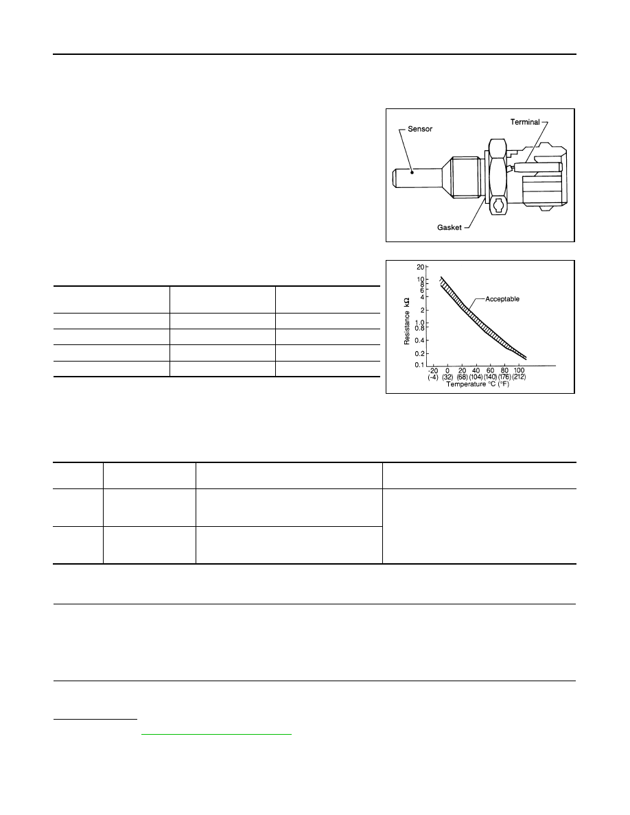
The engine coolant temperature sensor is used to detect the engine
coolant temperature. The sensor modifies a voltage signal from the
ECM. The modified signal returns to the ECM as the engine coolant
temperature input. The sensor uses a thermistor which is sensitive to
the change in temperature. The electrical resistance of the ther-
mistor decreases as temperature increases.
<Reference data>
*: These data are reference values and are measured between ECM terminals 71
(Engine coolant temperature sensor) and 84 (Sensor ground).
DTC Logic
INFOID:0000000003133333
DTC DETECTION LOGIC
DTC CONFIRMATION PROCEDURE
1.
PRECONDITIONING
If DTC Confirmation Procedure has been previously conducted, always turn ignition switch OFF and wait at
least 10 seconds before conducting the next test.
>> GO TO 2.
2.
PERFORM DTC CONFIRMATION PROCEDURE
1.
Turn ignition switch ON and wait at least 5 seconds.
2.
Check DTC.
Is DTC detected?
YES
>> Go to
NO
>> INSPECTION END
SEF594K
Engine coolant temperature
[
°
C (
°
F)]
Voltage*
(V)
Resistance
(k
Ω
)
–10 (14)
4.4
7.0 - 11.4
20 (68)
3.5
2.37 - 2.63
50 (122)
2.2
0.68 - 1.00
90 (194)
0.9
0.236 - 0.260
SEF012P
DTC No.
Trouble diagnosis
name
DTC detecting condition
Possible cause
P0117
Engine coolant tem-
perature sensor cir-
cuit low input
An excessively low voltage from the sensor is
sent to ECM.
• Harness or connectors
(The sensor circuit is open or shorted.)
• Engine coolant temperature sensor
P0118
Engine coolant tem-
perature sensor cir-
cuit high input
An excessively high voltage from the sensor is
sent to ECM.

P0117, P0118 ECT SENSOR
EC-173
< COMPONENT DIAGNOSIS >
[VQ35HR]
C
D
E
F
G
H
I
J
K
L
M
A
EC
N
P
O
Diagnosis Procedure
INFOID:0000000003133334
1.
CHECK GROUND CONNECTION
1.
Turn ignition switch OFF.
2.
Check ground connection M95. Refer to Ground Inspection in
Is the inspection result normal?
YES
>> GO TO 2.
NO
>> Repair or replace ground connection.
2.
CHECK ECT SENSOR POWER SUPPLY CIRCUIT
1.
Disconnect engine coolant temperature (ECT) sensor harness connector.
2.
Turn ignition switch ON.
3.
Check the voltage between ECT sensor harness connector and ground.
Is the inspection result normal?
YES
>> GO TO 4.
NO
>> GO TO 3.
3.
DETECT MALFUNCTIONING PART
Check the following.
• Harness connectors F106, F107
• Harness for open or short between engine coolant temperature sensor and ECM
>> Repair open circuit or short to ground or short to power in harness or connectors.
4.
CHECK ECT SENSOR GROUND CIRCUIT FOR OPEN AND SHORT
1.
Turn ignition switch OFF.
2.
Disconnect ECM harness connector.
3.
Check the continuity between ECT sensor harness connector and ECM harness connector.
4.
Also check harness for short to ground and short to power.
Is the inspection result normal?
YES
>> GO TO 5.
NO
>> Repair open circuit or short to ground or short to power in harness or connectors.
5.
CHECK ENGINE COOLANT TEMPERATURE SENSOR
EC-174, "Component Inspection"
Is the inspection result normal?
YES
>> GO TO 6.
NO
>> Replace engine coolant temperature sensor.
6.
CHECK INTERMITTENT INCIDENT
GI-38, "Intermittent Incident"
.
>> INSPECTION END
ECT sensor
Ground
Voltage (V)
Connector
Terminal
F17
1
Ground
Approx. 5
ECT sensor
ECM
Continuity
Connector
Terminal
Connector
Terminal
F17
2
F102
84
Existed
Нет комментариевНе стесняйтесь поделиться с нами вашим ценным мнением.
Текст