Infiniti EX35. Manual — part 701
NOISE, VIBRATION AND HARSHNESS (NVH) TROUBLESHOOTING
EM-3
< SYMPTOM DIAGNOSIS >
C
D
E
F
G
H
I
J
K
L
M
A
EM
N
P
O
SYMPTOM DIAGNOSIS
NOISE, VIBRATION AND HARSHNESS (NVH) TROUBLESHOOTING
NVH Troubleshooting - Engine Noise
INFOID:0000000003139068
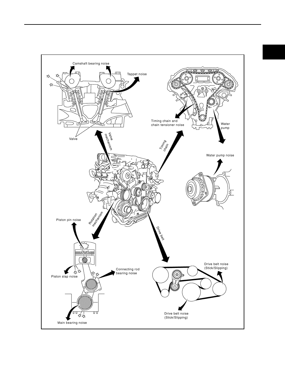
Use the Chart Below to Help You Find the Cause of the Symptom
INFOID:0000000003139069
1.
Locate the area where noise occurs.
JPBIA0001GB

EM-4
< SYMPTOM DIAGNOSIS >
NOISE, VIBRATION AND HARSHNESS (NVH) TROUBLESHOOTING
2.
Confirm the type of noise.
3.
Specify the operating condition of the engine.
4.
Check specified noise source.
If necessary, repair or replace these parts.
A: Closely related
B: Related
C: Sometimes related
—: Not related
Location
of noise
Type of
noise
Operating condition of engine
Source of
noise
Check item
Refer-
ence page
Before
warm-
up
After
warm-
up
When
start-
ing
When
idling
When
racing
While
driving
Top of en-
gine
Rocker
cover
Cylinder
head
Ticking or
clicking
C
A
—
A
B
—
Tappet
noise
Valve clearance
Rattle
C
A
—
A
B
C
Camshaft
bearing
noise
Camshaft runout
Camshaft journal oil
clearance
Crank-
shaft pul-
ley
Cylinder
block
(Side of
engine)
Oil pan
Slap or
knock
—
A
—
B
B
—
Piston pin
noise
Piston to piston pin oil
clearance
Connecting rod bushing
oil clearance
Slap or
rap
A
—
—
B
B
A
Piston
slap noise
Piston to cylinder bore
clearance
Piston ring side clear-
ance
Piston ring end gap
Connecting rod bend
and torsion
Knock
A
B
C
B
B
B
Connect-
ing rod
bearing
noise
Connecting rod bushing
oil clearance
Connecting rod bearing
oil clearance
Knock
A
B
—
A
B
C
Main bear-
ing noise
Main bearing oil clear-
ance
Crankshaft runout
Front of
engine
Timing
chain case
Tapping or
ticking
A
A
—
B
B
B
Timing
chain and
timing
chain ten-
sioner
noise
Timing chain cracks
and wear
Timing chain tensioner
operation
Front of
engine
Squeak-
ing or fizz-
ing
A
B
—
B
—
C
Drive belt
(Sticking
or slip-
ping)
Drive belt deflection
Creaking
A
B
A
B
A
B
Drive belt
(Slipping)
Idler pulley bearing op-
eration
Squall
Creak
A
B
—
B
A
B
Water
pump
noise
Water pump operation
PRECAUTIONS
EM-5
< PRECAUTION >
C
D
E
F
G
H
I
J
K
L
M
A
EM
N
P
O
PRECAUTION
PRECAUTIONS
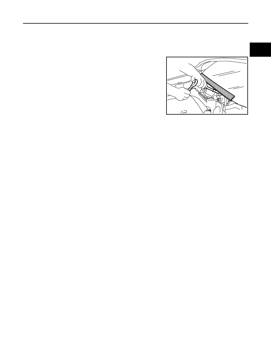
Precaution for Procedure without Cowl Top Cover
INFOID:0000000003554244
When performing the procedure after removing cowl top cover, cover
the lower end of windshield with urethane, etc.
Precaution for Supplemental Restraint System (SRS) "AIR BAG" and "SEAT BELT
PRE-TENSIONER"
INFOID:0000000003554243
The Supplemental Restraint System such as “AIR BAG” and “SEAT BELT PRE-TENSIONER”, used along
with a front seat belt, helps to reduce the risk or severity of injury to the driver and front passenger for certain
types of collision. This system includes seat belt switch inputs and dual stage front air bag modules. The SRS
system uses the seat belt switches to determine the front air bag deployment, and may only deploy one front
air bag, depending on the severity of a collision and whether the front occupants are belted or unbelted.
Information necessary to service the system safely is included in the “SRS AIRBAG” and “SEAT BELT” of this
Service Manual.
WARNING:
• To avoid rendering the SRS inoperative, which could increase the risk of personal injury or death in
the event of a collision which would result in air bag inflation, all maintenance must be performed by
an authorized NISSAN/INFINITI dealer.
• Improper maintenance, including incorrect removal and installation of the SRS, can lead to personal
injury caused by unintentional activation of the system. For removal of Spiral Cable and Air Bag
Module, see the “SRS AIRBAG”.
• Do not use electrical test equipment on any circuit related to the SRS unless instructed to in this
Service Manual. SRS wiring harnesses can be identified by yellow and/or orange harnesses or har-
ness connectors.
Precaution Necessary for Steering Wheel Rotation after Battery Disconnect
INFOID:0000000003657647
NOTE:
• Before removing and installing any control units, first turn the push-button ignition switch to the LOCK posi-
tion, then disconnect both battery cables.
• After finishing work, confirm that all control unit connectors are connected properly, then re-connect both
battery cables.
• Always use CONSULT-III to perform self-diagnosis as a part of each function inspection after finishing work.
If a DTC is detected, perform trouble diagnosis according to self-diagnosis results.
This vehicle is equipped with a push-button ignition switch and a steering lock unit.
If the battery is disconnected or discharged, the steering wheel will lock and cannot be turned.
If turning the steering wheel is required with the battery disconnected or discharged, follow the procedure
below before starting the repair operation.
OPERATION PROCEDURE
1.
Connect both battery cables.
NOTE:
Supply power using jumper cables if battery is discharged.
2.
Turn the push-button ignition switch to ACC position.
(At this time, the steering lock will be released.)
PIIB3706J
EM-6
< PRECAUTION >
PRECAUTIONS
3.
Disconnect both battery cables. The steering lock will remain released with both battery cables discon-
nected and the steering wheel can be turned.
4.
Perform the necessary repair operation.
5.
When the repair work is completed, re-connect both battery cables. With the brake pedal released, turn
the push-button ignition switch from ACC position to ON position, then to LOCK position. (The steering
wheel will lock when the push-button ignition switch is turned to LOCK position.)
6.
Perform self-diagnosis check of all control units using CONSULT-III.
Draining Engine Coolant
INFOID:0000000003139073
Drain engine coolant and engine oil when the engine is cooled.
Disconnecting Fuel Piping
INFOID:0000000003139074
• Before starting work, check no fire or spark producing items are in the work area.
• Release fuel pressure before disconnecting and disassembly.
• After disconnecting pipes, plug openings to stop fuel leakage.
Removal and Disassembly
INFOID:0000000003139075
• When instructed to use SST, use specified tools. Always be careful to work safely, avoid forceful or unin-
structed operations.
• Exercise maximum care to avoid damage to mating or sliding surfaces.
• Dowel pins are used for several parts alignment. When replacing and reassembling parts with dowel pins,
check that dowel pins are installed in the original position.
• Cover openings of engine system with a tape or equivalent, if necessary, to seal out foreign materials.
• Mark and arrange disassembly parts in an organized way for easy troubleshooting and re-assembly.
• When loosening nuts and bolts, as a basic rule, start with the one furthest outside, then the one diagonally
opposite, and so on. If the order of loosening is specified, do exactly as specified. Power tools may be used
in the step.
Inspection, Repair and Replacement
INFOID:0000000003139076
Before repairing or replacing, thoroughly inspect parts. Inspect new replacement parts in the same way, and
replace if necessary.
Assembly and Installation
INFOID:0000000003139077
• Use torque wrench to tighten bolts or nuts to specification.
• When tightening bolts and nuts, as a basic rule, equally tighten in several different steps starting with the
ones in center, then ones on inside and outside diagonally in this order. If the order of tightening is specified,
do exactly as specified.
• Replace with new gasket, packing, oil seal or O-ring.
• Dowel pins are used for several parts alignment. When replacing and reassembling parts with dowel pins,
check that dowel pins are installed in the original position.
• Thoroughly wash, clean, and air-blow each part. Carefully check engine oil or engine coolant passages for
any restriction and blockage.
• Avoid damaging sliding or mating surfaces. Completely remove foreign materials such as cloth lint or dust.
Before assembly, oil sliding surfaces well.
• Release air within route when refilling after draining engine coolant.
• After repairing, start the engine and increase engine speed to check engine coolant, fuel, engine oil, and
exhaust gases for leakage.
Parts Requiring Angle Tightening
INFOID:0000000003139078
• Use the angle wrench [SST: KV10112100 (BT8653-A)] for the final tightening of the following engine parts:
- Cylinder head bolts
- Lower cylinder block bolts
- Connecting rod cap bolts
• Do not use a torque value for final tightening.
• The torque value for these parts are for a preliminary step.
• Ensure thread and seat surfaces are clean and coated with engine oil.
Нет комментариевНе стесняйтесь поделиться с нами вашим ценным мнением.
Текст