Infiniti EX35. Manual — part 1062

DIAGNOSIS AND REPAIR WORKFLOW
MIR-3
< BASIC INSPECTION >
[WITH ADP]
C
D
E
F
G
H
I
J
K
M
A
B
MIR
N
O
P
BASIC INSPECTION
DIAGNOSIS AND REPAIR WORKFLOW
Work Flow
INFOID:0000000003136520
DETAILED FLOW
1.
OBTAIN INFORMATION ABOUT SYMPTOM
Interview the customer to obtain the malfunction information (conditions and environment when the malfunc-
tion occurred) as much as possible when the customer brings the vehicle in.
>> GO TO 2.
2.
CHECK DTC
Perform self-diagnosis for automatic drive positioner (ADP) with CONSULT-III.
Is any DTC detected?
YES
>> Refer to
NO
>> GO TO 3.
3.
REPRODUCE THE MALFUNCTION INFORMATION
Check the malfunction on the vehicle that the customer describes.
Inspect the relation of the symptoms and the condition when the symptoms occur.
>> GO TO 4.
4.
IDENTIFY THE MALFUNCTIONING SYSTEM WITH “SYMPTOM DIAGNOSIS”
Use “Symptom diagnosis” from the symptom inspection result in step 3. Then identify where to start perform-
ing the diagnosis based on possible causes and symptoms.
>> GO TO 5.
5.
IDENTIFY MALFUNCTIONING PARTS WITH “COMPONENT DIAGNOSIS”
Perform the diagnosis with “Component diagnosis” of the applicable system.
>> GO TO 6.
6.
REPAIR OR REPLACE THE MALFUNCTIONING PARTS
Repair or replace the specified malfunctioning parts.
>> GO TO 7.
7.
FINAL CHECK
Check that malfunctions are not reproduced when obtaining the malfunction information from the customer,
referring to the symptom inspection result in step 3.
Are all malfunctions corrected?
YES
>> INSPECTION END
NO
>> GO TO 4.
MIR-4
< FUNCTION DIAGNOSIS >
[WITH ADP]
DOOR MIRROR SYSTEM
FUNCTION DIAGNOSIS
DOOR MIRROR SYSTEM
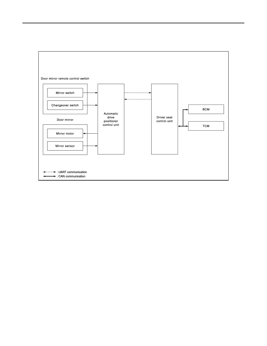
System Diagram
INFOID:0000000003136521
System Description
INFOID:0000000003136522
MANUAL FUNCTION
Description
• Automatic drive positioner control unit controls door mirror.
• Automatic drive positioner control unit inputs changeover switch signal and perform the LH/RH control of
door mirror motor supplying electric power when changeover switch is operated.
• Automatic drive positioner control unit inputs mirror switch signal and supplies electric power to door mirror.
• The ignition switch signal (ACC/ON) is transmitted from BCM to the driver seat control unit via CAN commu-
nication and from the driver seat control unit to the automatic drive positioner control unit via UART commu-
nication.
Operation Conditions
If the following conditions are not satisfied, operation is not performed.
• Ignition switch: ON or ACC
• Changeover switch: Select either left or right
REVERSE INTERLOCK DOOR MIRROR SYSTEM
Description
• Select one of the door mirror faces by change over switch, and then set the selected mirror face downward/
inward.
• When the ignition switch is ON position and control device is in R position, the TCM sends the R signal to the
driver seat control unit. The R signal is transmitted to the automatic drive positioner control unit from the
driver seat control unit via UART communication. When the R signal is detected, the automatic device posi-
tioner control unit activated the mirror motor.
Operation Conditions
If the following conditions are not satisfied, operation is not performed.
JMLIA0133GB
DOOR MIRROR SYSTEM
MIR-5
< FUNCTION DIAGNOSIS >
[WITH ADP]
C
D
E
F
G
H
I
J
K
M
A
B
MIR
N
O
P
• Ignition switch: ON
• Changeover switch: Select either left or right
• A/T control device: R position
During the reverse interlock door mirror system, if all of the above conditions are not satisfied, mirror face
returns to original angle.
Mirror Angle Memory Function
• During the reverse interlock door mirror operation, the mirror angle can be changed. After adjustment, the
mirror face positions can be memorized (2 positions). For memory setting.
• Initial setting is downward 7
°
, inward 1
°
(both of left and right).
• When the driver's seat, outside mirror and steering column are not in the memorized position, the outside
mirror will move with the initial tilt-down angle, if the reverse tilt-down position is stored. Linking Intelligent
Key to a stored memory position.
Memory Procedure
1.
Apply the parking brake.
2.
Push the ignition switch to the ON position. (Do not start the engine.)
3.
Push the memory switch 1 or 2 fully for at least 1 second to operate the automatic drive positioner.
4.
Turn the door mirror control switch (changeover switch) to L (left).
5.
Depress the brake pedal.
6.
Move the control device to R position (reverse).
7.
Adjust the mirror to the desired viewing position for backing up by operating the door mirror control switch
(mirror switch).
8.
Push the SET switch and, within 5 seconds, push the memory switch 1 or 2 selected in step 3 fully for at
least 1 second.
The indicator light for the pushed memory switch will come on and stay pushing the switch. After the indi-
cator light goes off, the selected mirror position is stored in the selected memory (1 or 2).
9.
Turn the door mirror control switch (changeover switch) to R (right).
Repeat the above procedure to adjust the right mirror position and store in the selected memory.
AUTOMATIC DRIVE POSITIONER SYSTEM LINKED OPERATION
Description
Door mirror control is included in automatic drive positioner system. Refer to automatic drive positioner system
for more details.
Refer to
ADP-14, "AUTOMATIC DRIVE POSITIONER SYSTEM : System Description"
.
MIR-6
< FUNCTION DIAGNOSIS >
[WITH ADP]
DOOR MIRROR SYSTEM
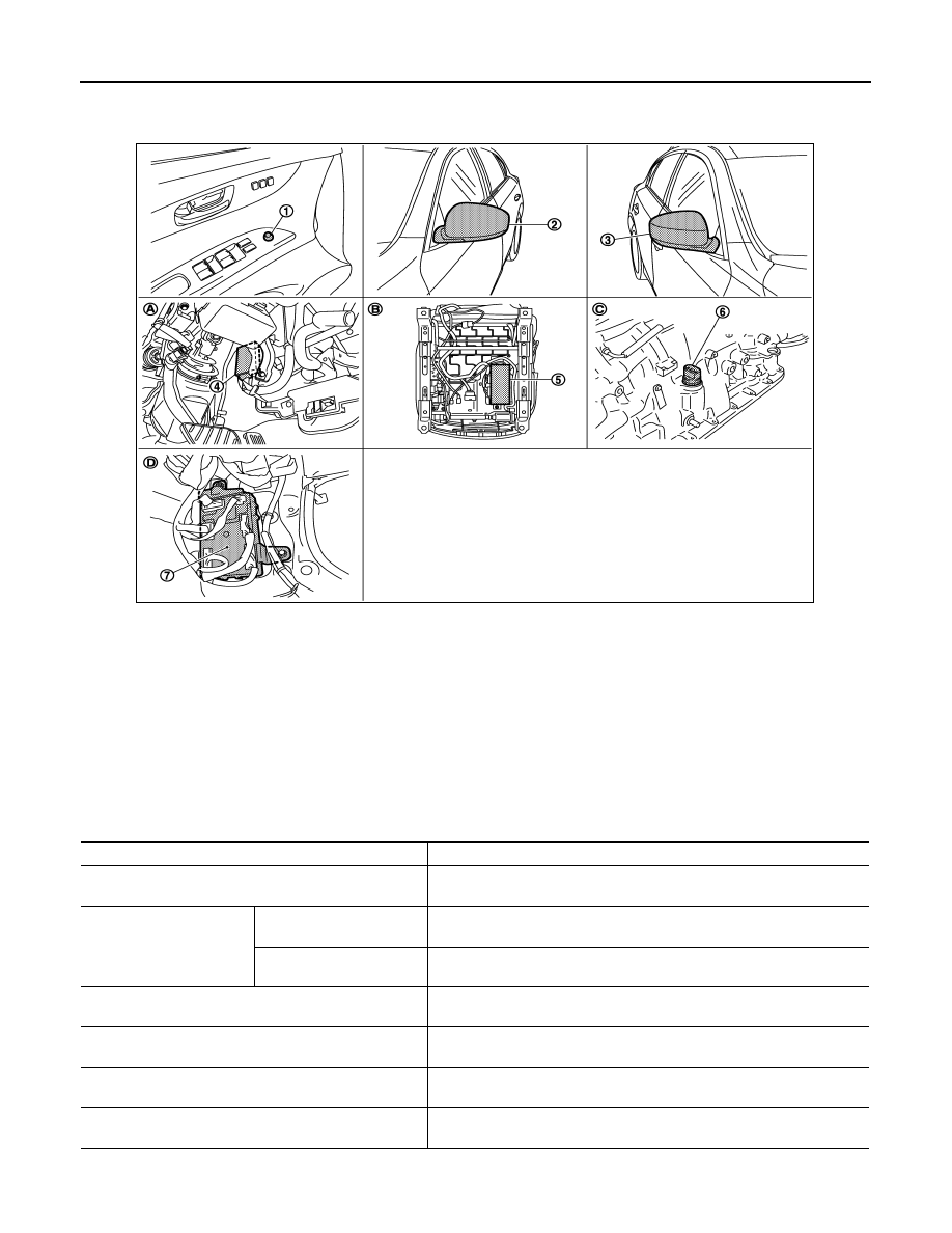
Component Parts Location
INFOID:0000000003136523
Component Description
INFOID:0000000003136524
1.
Door mirror remote control switch
D17
2.
Door mirror (driver side) D3
3.
Door mirror (passenger side) D33
4.
Automatic drive positioner control
unit M51, M52
5.
Driver seat control unit B451, B452
6.
AT assembly connector (TCM) F51
7.
BCM M118, M119, M122
A.
View with instrument driver lower
panel removed
B.
Back side of the seat cushion
C.
AT assembly (TCM is built in AT as-
sembly)
D.
Dash side lower (passenger side)
JMLIA0129ZZ
Component
Function
Automatic drive positioner control unit
Door mirror is supplied with power after receiving the input of the MIRROR
SWITCH and CHANGEOVER SWITCH.
Door mirror remote control
switch
Mirror switch
It transmits mirror face adjust operation to AUTOMATIC DRIVE POSI-
TIONER CONTROL UNIT.
Changeover switch
It transmits the LH/RH control of door mirror that supplies power to AUTO-
MATIC DRIVE POSITIONER CONTROL UNIT.
Door mirror
It makes mirror face operate from side to side and up and down via inte-
grated motor.
BCM
The ignition switch signal (ACC/ON) is transmitted to driver seat control
unit via CAN communication.
Driver seat control unit
The ignition switch signal (ACC/ON) is transmitted to automatic drive posi-
tioner control unit via UART communication.
TCM
The A/T shift position signal is transmitted to driver seat control unit via
CAN communication.
Нет комментариевНе стесняйтесь поделиться с нами вашим ценным мнением.
Текст