Infiniti EX35. Manual — part 277
AV
MULTI AV SYSTEM SYMPTOMS
AV-889
< SYMPTOM DIAGNOSIS >
[BOSE AUDIO WITH NAVIGATION]
C
D
E
F
G
H
I
J
K
L
M
B
A
O
P
SYMPTOM DIAGNOSIS
MULTI AV SYSTEM SYMPTOMS
Symptom Table
INFOID:0000000003459047
RELATED TO NAVIGATION
Trouble diagnosis chart by symptom
RELATED TO HANDS-FREE PHONE
• Check that the cellular phone is corresponding type (Bluetooth
®
correspond) when the hands-free related
malfunction vehicle is in service before performing a diagnosis.
• There is a case that malfunction occurs due to the version change of the phone type, etc. even though it is a
corresponding type. Therefore, confirm it by changing the cellular phone to another corresponding type
phone, and check that it operates normally. It is necessary to distinguish whether the cause is the vehicle or
cellular phone.
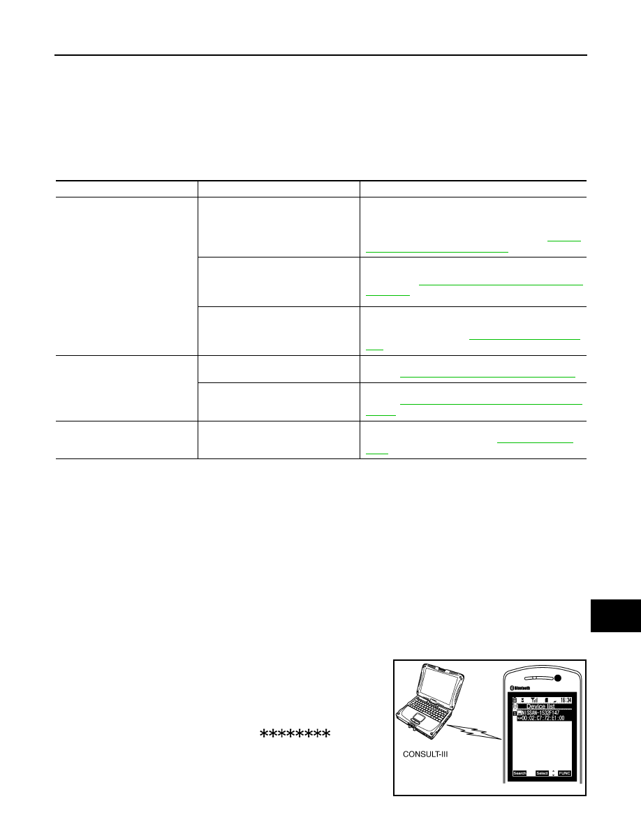
Simple check for Bluetooth
®
communication
If cellular phone and AV control unit cannot be connected with Bluetooth
®
communication, following procedure
allows the technician to judge which device has malfunction.
1.
Turn on a cellular phone, not connecting Bluetooth
®
communication.
2.
Start CONSULT-III, then start Windows
®
.
3.
Set CONSULT-III near a cellular phone.
4.
When operated Bluetooth
®
registration by cellular phone, check
if CONSULT-III
*
would be displayed on the device name.
(If other Bluetooth
®
device is located near cellular phone, a
name of the device would be displayed also.)
NOTE:
*:Displayed device name is “NISSAN-
”.
• If no device name is displayed, cellular phone is malfunctioning.
Repair the cellular phone first, then perform diagnosis.
• If CONSULT-III is displayed on device name, cellular phone is nor-
mal. Perform diagnosis as per the following table.
Symptoms
Check items
Possible malfunction location / Action to take
Multifunction switch and preset
switch operation does not work.
• All switches cannot be operated.
• “MULTI AV” is displayed on system
selection screen when the CON-
SULT-III is started.
• Multifunction switch power supply and ground circuit.
• AV communication circuit between AV control unit and
multifunction switch.
Perform CONSULT-III self-diagnosis. Refer to
"CONSULT-III Function (MULTI AV)"
.
• All switches cannot be operated.
• “MULTI AV” is not displayed on sys-
tem selection screen when the CON-
SULT-III is initialized.
AV control unit power supply and ground circuit malfunc-
tion. Refer to
AV-544, "AV CONTROL UNIT : Diagnosis
.
Only specified switch cannot be operat-
ed.
Multifunction switch or preset switch malfunction.
Perform multifunction switch and preset switch self-di-
agnosis function. Refer to
.
Fuel economy display, vehicle set-
ting operation is abnormal.
There is malfunction in the CONSULT-
III self-diagnosis result.
Perform detected DTC self-diagnosis.
Refer to
AV-498, "CONSULT-III Function (MULTI AV)"
.
There is no malfunction in the self-diag-
nosis results.
Ignition signal circuit malfunction.
Refer to
AV-544, "AV CONTROL UNIT : Diagnosis Pro-
.
Guide sound is not heard.
On the setting display select “system
sound (guide sound volume, etc.),” and
confirm that guide sound is ON.
AV control unit malfunction.
Replace AV control unit. Refer to
JPNIA0441GB

AV-890
< SYMPTOM DIAGNOSIS >
[BOSE AUDIO WITH NAVIGATION]
MULTI AV SYSTEM SYMPTOMS
Trouble diagnosis chart by symptom
RELATED TO REAR VIEW MONITOR
Trouble diagnosis chart by symptom
Symptoms
Check items
Probable malfunction location
Does not recognize cellular
phone connection. (no connec-
tion is displayed on the display
at the guide.)
Repeat the registration of cellular phone.
AV control unit malfunction.
Replace AV control unit. Refer to
Hands-free phone cannot be
established.
• Hands-free phone operation can be
made, but the communication cannot
be established.
• Hands-free phone operation can be
performed, however, voice between
each other cannot be heard during the
conversation.
AV control unit malfunction.
Replace AV control unit. Refer to
The other party's voice cannot
be heard by hands-free phone.
Check the “microphone speaker” in “Con-
firmation/Adjustment” mode if sound is
heard.
AV control unit malfunction.
Replace AV control unit. Refer to
Check the “microphone speaker” in “Con-
firmation/Adjustment” mode if sound is not
heard.
AV control unit malfunction.
Replace AV control unit. Refer to
Originating sound is not heard
by the other party with hands-
free phone communication.
Sound operation function is normal.
AV control unit malfunction.
Replace AV control unit. Refer to
Sound operation function does not work.
Microphone signal circuit malfunction.
Refer to
.
Symptoms
Check items
Probable malfunction location
Camera image is not displayed
(displayed in black and nothing
can be displayed)
AUX image is not displayed.
• Horizontal synchronizing (HP) signal circuit malfunc-
tion between AV control unit and display unit.
Refer to
• Vertical synchronizing (VP) signal circuit malfunction
between AV control unit and display unit.
Refer to
Camera image is not shown.
(Guiding line is displayed.)
—
• Camera image signal circuit between camera control
unit and rear view camera.
• Rear view camera power supply circuit.
Refer to
Camera image is not displayed.
(Only warning message under
area is displayed.)
There is malfunction in the CONSULT-III
self-diagnosis result.
Perform detected DTC self-diagnosis.
Refer to
AV-498, "CONSULT-III Function (MULTI AV)"
AUX image is normal.
Camera image signal circuit malfunction between cam-
era control unit and display unit.
Refer to
AV-564, "WITH REAR VIEW MONITOR : Diag-
AUX image is not displayed.
RGB area (YS) signal circuit malfunction between AV
control unit and display unit.
Refer to
.
Select “Camera Cont.” of “Confirmation/
Adjustment” mode, Reverse Sensor is not
turned ON at “Connection Confirmation”.
Reverse signal circuit (camera control unit).
Camera image is rolling.
AUX image is also rolling.
Vertical synchronizing (VP) signal circuit malfunction be-
tween AV control unit and display unit.
Refer to
.
AV
MULTI AV SYSTEM SYMPTOMS
AV-891
< SYMPTOM DIAGNOSIS >
[BOSE AUDIO WITH NAVIGATION]
C
D
E
F
G
H
I
J
K
L
M
B
A
O
P
RELATED TO AROUND VIEW MONITOR
Camera image does not switch.
Malfunction of self-diagnosis result is indi-
cated.
Camera-connection recognition signal circuit
Refer to
AV-498, "CONSULT-III Function (MULTI AV)"
Malfunction of self-diagnosis result is not
indicated.
Reverse signal circuit (AV control unit).
Possible route line is indicated
abnormally when camera im-
age is displayed.
—
Sensor signal circuit malfunction.
Refer to
AV-567, "WITH REAR VIEW MONITOR : Diag-
Symptoms
Check items
Probable malfunction location
Symptoms
Check items
Probable malfunction location / Action
to take
It does not switch to camera image
even when the “CAMERA” switch is
pressed or the selector lever is in the
reverse position.
“Camera Cont.” of “Confirmation/Adjustment” can be
selected.
Ignition signal circuit.
“Camera Cont.” of “Confirmation/Adjustment” cannot
be selected.
• Around view monitor control unit
power supply and ground circuits.
Refer to
MONITOR CONTROL UNIT : Diag-
nosis Procedure"
.
• AV communication circuits.
Refer to
The screen switches when pressing
the “CAMERA” switch or shifting the
selector lever to the reverse posi-
tion, however, all views are not dis-
played.
Only superimposing is displayed.
(Only the image displayed by AV control unit is dis-
played)
• Camera image signal circuit between
around view monitor control unit and
display unit.
Refer to
MONITOR CONTROL UNIT : Diag-
nosis Procedure"
.
• RGB (YS) area signal circuit.
Refer to
Superimposing is not displayed.
Communication circuit between AV
control unit and display unit.
Refer to
When detecting no malfunction in those
components, the following items are a
possible cause.
• Horizontal synchronizing (HP) signal
circuit malfunction between AV con-
trol unit and display unit.
Refer to
• Vertical synchronizing (VP) signal cir-
cuit malfunction between AV control
unit and display unit.
Refer to
Camera image is rolling.
AUX image is rolling
• Horizontal synchronizing (HP) signal
circuit malfunction between AV con-
trol unit and display unit.
Refer to
• Vertical synchronizing (VP) signal cir-
cuit malfunction between AV control
unit and display unit.
Refer to
It cannot be switched to rear view
monitor even when the selector le-
ver is in the reverse position.
The front view is displayed normally.
Reverse signal circuit. (AV control unit)

AV-892
< SYMPTOM DIAGNOSIS >
[BOSE AUDIO WITH NAVIGATION]
MULTI AV SYSTEM SYMPTOMS
RELATED TO CAMERA ASSISTANCE SONAR
The predicted course line display in
front view and rear view is malfunc-
tioning.
The “Steer. Angle Sensor” is not turned ON at “Con-
nection Confirmation” of “Camera Cont.”
Steering angle sensor signal circuits.
Refer to
MONITOR : Diagnosis Procedure"
• The front view screen is not dis-
played.
• The front of Birds-Eye view
screen is not displayed.
Check the item Front
Camera in “Connec-
tion Confirmation”
mode of “Camera
Cont.”
• Image Output Signal: NG
• COMM Status: NG
• COMM Line: NG
• Front camera image signal circuit.
• Front camera power supply and
ground circuits.
Refer to
• Image Output Signal: OK
• COMM Status: NG
• COMM Line: NG
Front camera communication signal cir-
cuit. Refer to
• The rear view screen is not dis-
played.
• The rear of Birds-Eye view screen
is not displayed.
Check the item Rear
Camera in “Connec-
tion Confirmation”
mode of “Camera
Cont.”
• Image Output Signal: NG
• COMM Status: NG
• COMM Line: NG
• Rear camera image signal circuit.
• Rear camera power supply and
ground circuits.
Refer to
.
• Image Output Signal: OK
• COMM Status: NG
• COMM Line: NG
Rear camera communication signal
circuits. Refer to
.
• The front-side screen is not dis-
played.
• The side RH of Birds-Eye view
screen is not displayed.
Check the item Pass-
Side Camera in “Con-
nection Confirmation”
mode of “Camera
Cont.”
• Image Output Signal: NG
• COMM Status: NG
• COMM Line: NG
• Side camera RH image signal circuit.
• Side camera RH power supply and
ground circuits.
Refer to
.
• Image Output Signal: OK
• COMM Status: NG
• COMM Line: NG
Side camera RH communication circuit.
Refer to
.
The side LH of Birds-eye view
screen is not displayed.
Check the item Dr-
Side Camera at “Con-
nection Confirmation”
mode of “Camera
Cont.”
• Image Output Signal: NG
• COMM Status: NG
• COMM Line: NG
• Side camera LH image signal circuit.
• Side camera LH power supply and
ground circuits.
Refer to
.
• Image Output Signal: OK
• COMM Status: NG
• COMM Line: NG
Side camera LH communication circuit.
Refer to
.
When shift position is other than “R”
the front-side and front screen or the
Birds-Eye view and front screen re-
main displaying even if the vehicle
speed increases.
—
Vehicle speed signal (around view
monitor control unit).
Around view monitor does not start
other than shift position “R”
—
Certain States restrict the operation so
that around view monitor does not start
other than at shift position "R".
Symptoms
Check items
Probable malfunction location / Action
to take
Нет комментариевНе стесняйтесь поделиться с нами вашим ценным мнением.
Текст