Infiniti EX35. Manual — part 430
DEF-4
< FUNCTION DIAGNOSIS >
REAR WINDOW DEFOGGER SYSTEM
FUNCTION DIAGNOSIS
REAR WINDOW DEFOGGER SYSTEM
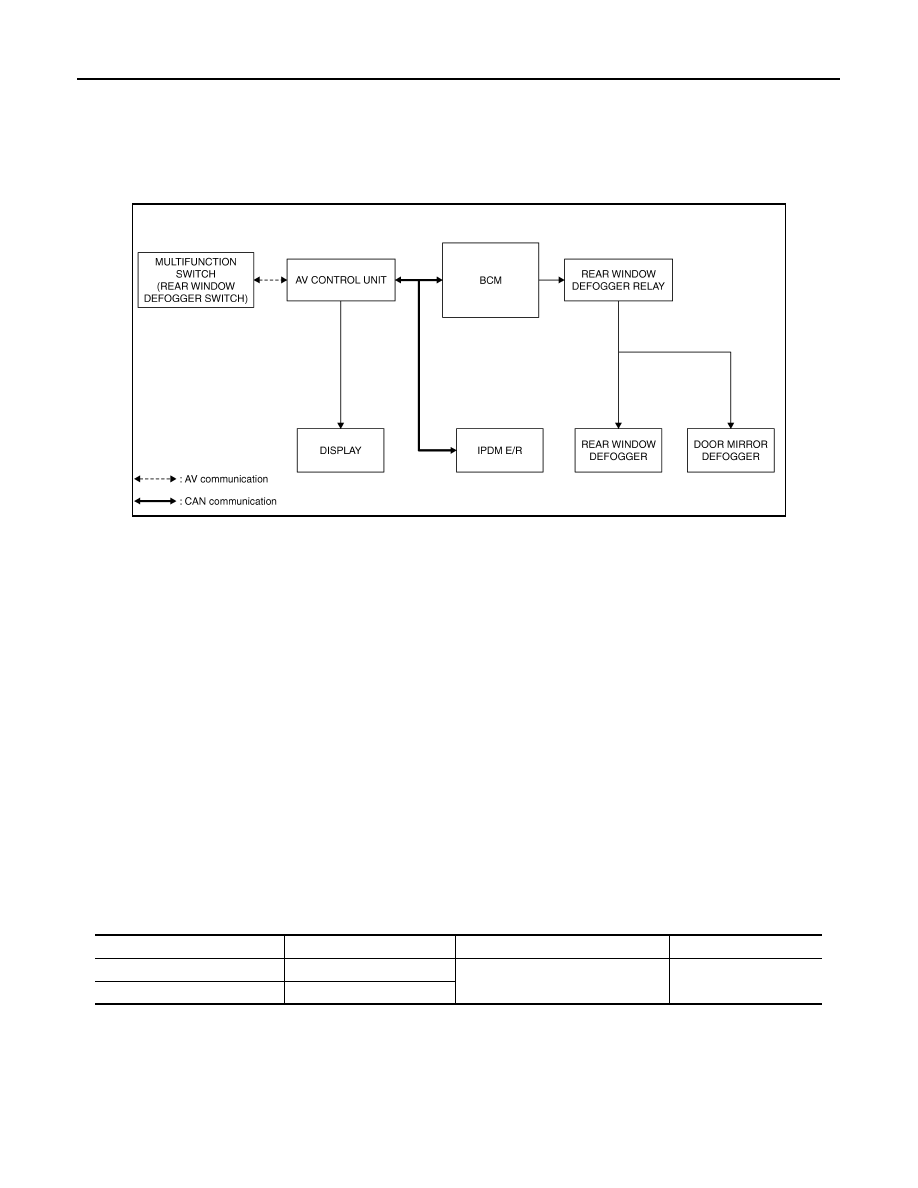
System Diagram
INFOID:0000000003136641
System Description
INFOID:0000000003136642
Operation Description
• Turn rear window defogger switch ON when the ignition switch is turned ON. Then multifunction switch (rear
window defogger switch) transmits rear window defogger switch signal to AV control unit via AV communica-
tion. AV control unit transmits rear window defogger switch signal to BCM via CAN communication.
• BCM turns rear window defogger relay ON and transmits rear window defogger control signal to IPDM E/R
via CAN communication when rear window defogger switch signal is received.
• Rear window defogger and door mirror defogger (with mirror defogger) are supplied with power and operate
when rear window defogger relay turns ON.
• IPDM E/R transmits rear window defogger control signal to AV control unit via CAN communication.
• AV control unit transmit rear defogger indicator signal to multifunction switch (rear window defogger switch)
via AV communication then rear window defogger indicator is illuminated.
Timer function
• BCM turns rear window defogger relay ON for approximately 15 minutes when rear window defogger switch
is turned ON. It makes rear window defogger and door mirror defogger (with mirror defogger) operate.
• Timer is canceled after pressing rear window defogger switch again during timer operation. Then BCM turns
rear window defogger relay OFF. The same reaction also occurs during timer operation, if the ignition switch
is turned OFF.
INPUT/OUTPUT SIGNAL CHART
*: With mirror defogger
JMLIA0005GB
Switch
Input signal to BCM
BCM function
Actuator
Rear window defogger switch
Defogger switch signal
Rear window defogger & Door mir-
ror defogger
*
control
Rear window defogger
Door mirror defogger
*
Push button ignition switch
Ignition signal
REAR WINDOW DEFOGGER SYSTEM
DEF-5
< FUNCTION DIAGNOSIS >
C
D
E
F
G
H
I
J
K
M
A
B
DEF
N
O
P
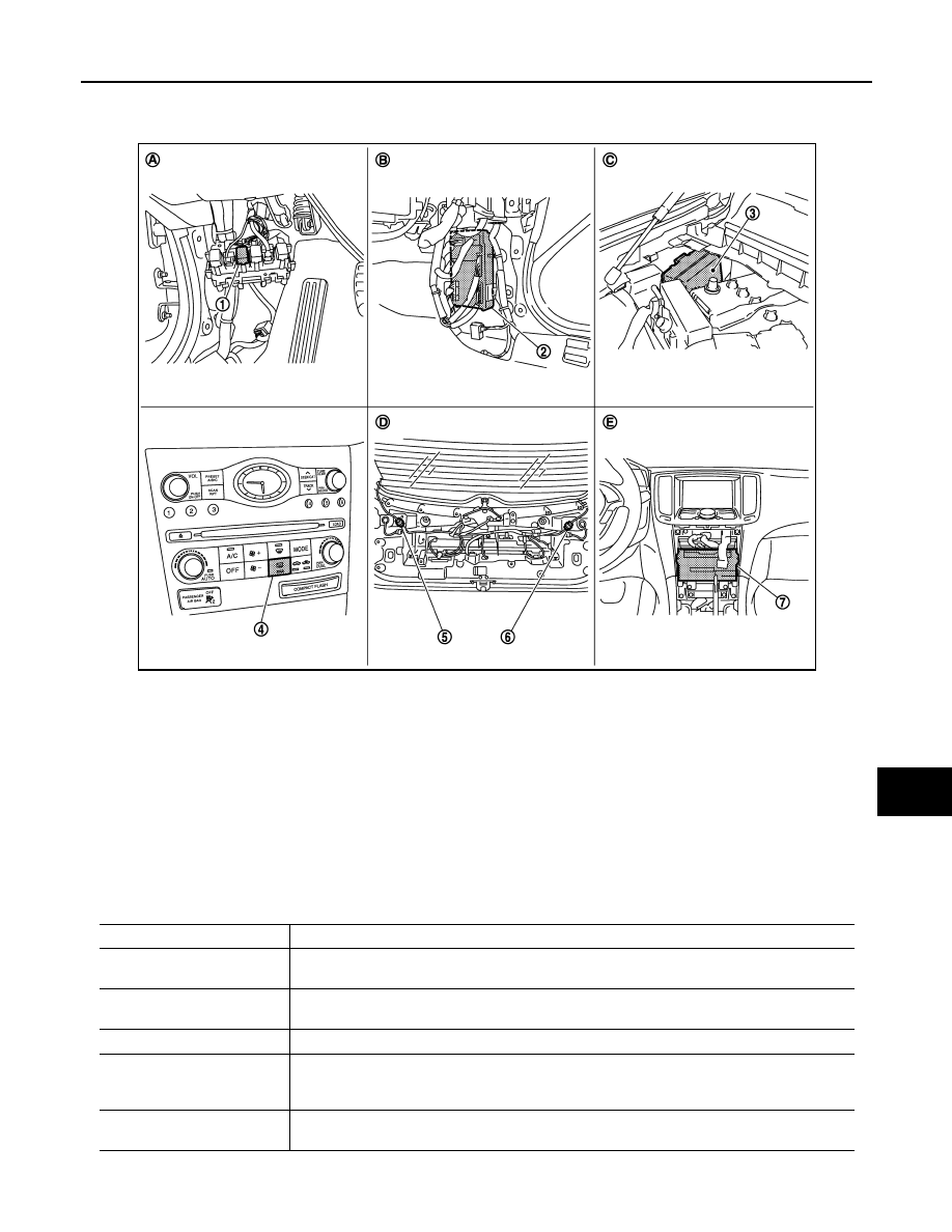
Component Parts Location
INFOID:0000000003136643
Component Description
INFOID:0000000003136644
1.
Rear window defogger relay (built-in
relay box)
2.
BCM M118, M119, M122, M123
3.
IPDM E/R E6
4.
Rear window defogger switch (built-in
multifunction switch M72)
5.
Rear window defogger connector
D108
6.
Rear window defogger connector
D120
7.
AV control unit
• With NAVI M87,M88
• Without NAVI M83, M85
A.
Dash side lower (driver side)
B.
Dash side lower (passenger side)
C.
Engine room dash panel (RH)
D.
Behind back door finisher
E.
Behind cluster lid C
JMLIA0125ZZ
Item
Function
BCM
• Operates the rear window defogger with the operation of rear window defogger switch.
• Performs the timer control of rear window defogger.
Rear window defogger relay
• Operates the rear window defogger and the door mirror defogger with the control signal from
BCM.
IPDM E/R
• Transmit rear window defogger control signal to AV control unit via CAN communication.
Multifunction switch
(Rear window defogger
switch)
• The rear window defogger switch is installed.
• Turns the indicator lamp ON when detecting the operation of rear window defogger.
AV control unit
• Displays the rear window defogger ON to the display when detecting the operation of rear win-
dow defogger.
DEF-6
< FUNCTION DIAGNOSIS >
REAR WINDOW DEFOGGER SYSTEM
*:
With mirror defogger
Rear window defogger
• Heats the heating wire with the power supply from the rear window defogger relay to prevent
the rear window from fogging up.
Door mirror defogger
*
• Heats the heating wire with the power supply from the rear window defogger relay to prevent
the door mirror from fogging up.
DIAGNOSIS SYSTEM (BCM)
DEF-7
< FUNCTION DIAGNOSIS >
C
D
E
F
G
H
I
J
K
M
A
B
DEF
N
O
P
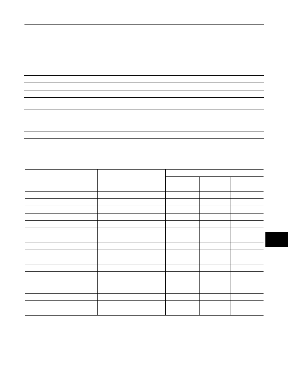
DIAGNOSIS SYSTEM (BCM)
COMMON ITEM
COMMON ITEM : CONSULT-III Function (BCM - COMMON ITEM)
INFOID:0000000003136645
APPLICATION ITEM
CONSULT-III performs the following functions via CAN communication with BCM.
SYSTEM APPLICATION
BCM can perform the following functions for each system.
NOTE:
It can perform the diagnosis modes except the following for all sub system selection items.
×
: Applicable item
*: This item is displayed, but is not used.
FREEZE FRAME DATA (FFD) AND IGN COUNTER
Freeze Frame Data
The BCM records the following condition at the moment a particular DTC is detected.
• Vehicle Speed
• Odo/Trip Meter
Diagnosis mode
Function Description
Work Support
Changes the setting for each system function.
Self Diagnostic Result
Displays the diagnosis results judged by BCM.
CAN Diag Support Monitor
Monitors the reception status of CAN communication viewed from BCM. Refer to CONSULT-III opera-
tion manual.
Data Monitor
The BCM input/output signals are displayed.
Active Test
The signals used to activate each device are forcibly supplied from BCM.
Ecu Identification
The BCM part number is displayed.
Configuration
This function is not used even though it is displayed.
System
Sub system selection item
Diagnosis mode
Work Support
Data Monitor
Active Test
Door lock
DOOR LOCK
×
×
×
Rear window defogger
REAR DEFOGGER
×
×
Warning chime
BUZZER
×
×
Interior room lamp timer
INT LAMP
×
×
×
Exterior lamp
HEAD LAMP
×
×
×
Wiper and washer
WIPER
×
×
×
Turn signal and hazard warning lamps
FLASHER
×
×
×
—
AIR CONDITIONER*
×
Intelligent Key system
INTELLIGENT KEY
×
×
×
Combination switch
COMB SW
×
Body control system
BCM
×
IVIS - NATS
IMMU
×
×
Interior room lamp battery saver
BATTERY SAVER
×
×
×
Trunk open
TRUNK
×
Vehicle security system
THEFT ALM
×
×
×
RAP system
RETAINED PWR
×
Signal buffer system
SIGNAL BUFFER
×
×
TPMS
TPMS (AIR PRESSURE MONITOR)
×
×
×
Нет комментариевНе стесняйтесь поделиться с нами вашим ценным мнением.
Текст