Infiniti EX35. Manual — part 428
WATER INLET AND THERMOSTAT ASSEMBLY
CO-21
< ON-VEHICLE REPAIR >
C
D
E
F
G
H
I
J
K
L
M
A
CO
N
P
O
WATER INLET AND THERMOSTAT ASSEMBLY
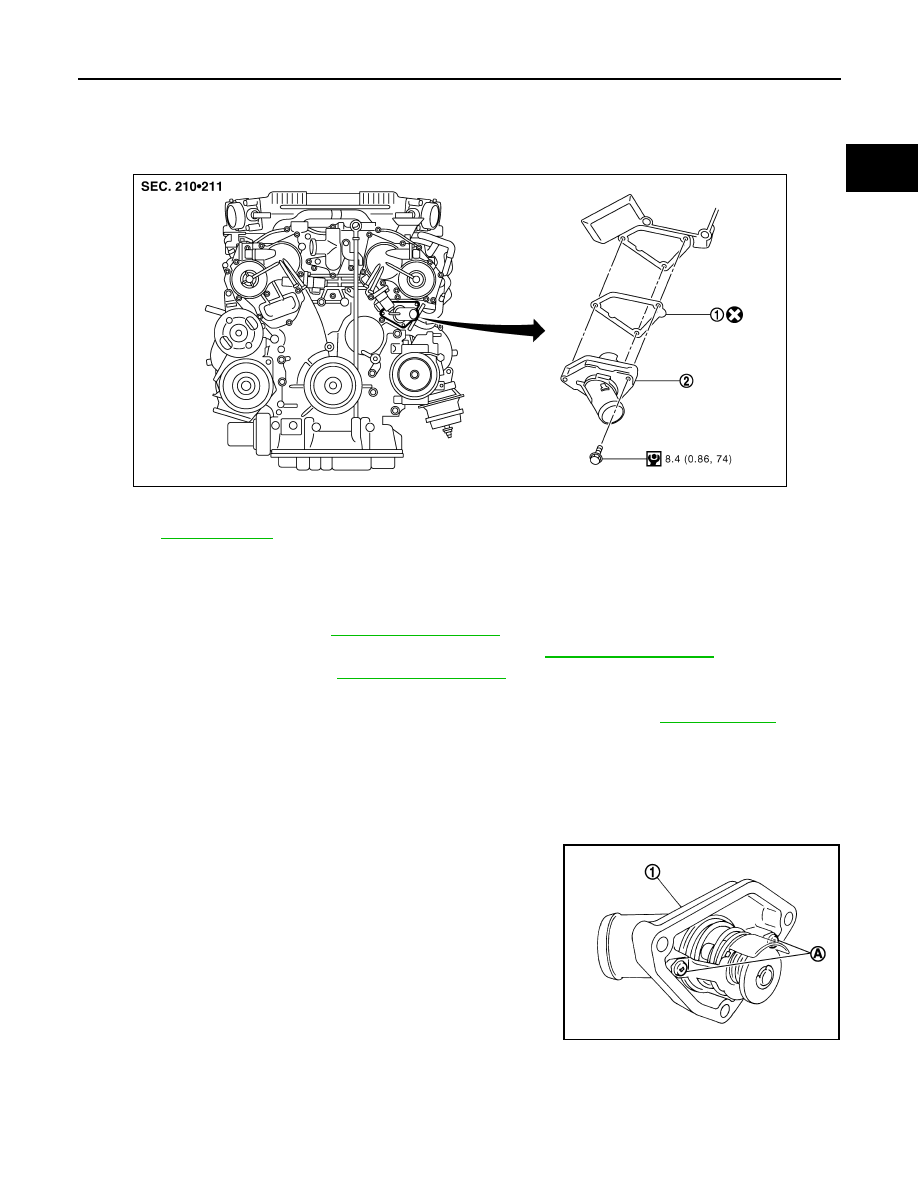
Exploded View
INFOID:0000000003139297
Removal and Installation
INFOID:0000000003139298
REMOVAL
1.
Remove engine cover. Refer to
.
2.
Remove air duct and air cleaner case assembly (LH). Refer to
.
3.
Remove reservoir tank. Refer to
.
4.
Remove engine undercover with power tool.
5.
Drain engine coolant from radiator drain plug at the bottom of radiator. Refer to
CAUTION:
• Perform this step when the engine is cold.
• Never spill engine coolant on drive belt.
6.
Disconnect radiator hose (lower).
7.
Disconnect intake valve timing control solenoid valve harness connector (bank 2), and remove intake
valve timing control solenoid valve.
8.
Remove water inlet and thermostat assembly (1).
CAUTION:
Never disassemble water inlet and thermostat assembly.
Replace them as a unit, if necessary.
INSTALLATION
Note the following, and install in the reverse order of removal.
• Be careful not to spill engine coolant over engine room. Use rag to absorb engine coolant.
1.
Gasket
2.
Water inlet and thermostat assembly
Refer to
for symbols in the figure.
JPBIA1466GB
A
: Never loosen these screw.
JPBIA0261ZZ
CO-22
< ON-VEHICLE REPAIR >
WATER INLET AND THERMOSTAT ASSEMBLY
Inspection
INFOID:0000000003139299
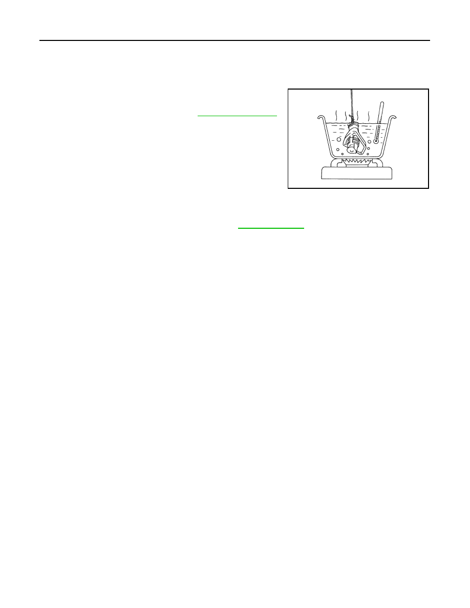
INSPECTION AFTER REMOVAL
1.
Check valve seating condition at ordinary room temperatures. It should seat tightly.
2.
Check valve operation.
• If the malfunctioning condition, when valve seating at ordinary
room temperature, or measured values are out of the standard,
replace water inlet and thermostat assembly.
INSPECTION AFTER INSTALLATION
• Check that the reservoir tank cap is tightened.
• Check for leakage of engine coolant using the radiator cap tester adapter (commercial service tool) and the
radiator cap tester (commercial service tool). Refer to
.
• Start and warm up the engine. Visually check that there is no leakage of engine coolant.
Thermostat (Standard)
: Refer to
.
SLC949A

WATER OUTLET AND WATER PIPING
CO-23
< ON-VEHICLE REPAIR >
C
D
E
F
G
H
I
J
K
L
M
A
CO
N
P
O
WATER OUTLET AND WATER PIPING
Exploded View
INFOID:0000000003139300
Removal and Installation
INFOID:0000000003139301
REMOVAL
1.
Remove engine undercover with power tool.
2.
Drain engine coolant. Refer to
CAUTION:
• Perform this step when the engine is cold.
• Never spill engine coolant on drive belt.
3.
Remove engine cover. Refer to
.
1.
Clamp
2.
Water hose
3.
Harness bracket
4.
Engine coolant temperature sensor
5.
Heater hose
6.
Clamp
7.
Water outlet (rear)
8.
Gasket
9.
O-ring
10. Water outlet pipe
11.
Water outlet (front)
12.
Radiator cap
13. Clamp
14.
Radiator hose (upper)
15.
Gasket
16. Heater pipe
17.
Clamp
18.
Water hose
19. Water bypass pipe
20.
Clamp
21.
Water hose
22. Heater hose
23.
O-ring
A.
To EVAP piping
B.
To heater core
C.
To radiator
D.
To electric throttle control actuator
(bank 2)
Refer to
for symbols in the figure.
JPBIA1834GB

CO-24
< ON-VEHICLE REPAIR >
WATER OUTLET AND WATER PIPING
4.
Remove air duct and air cleaner case assembly (RH and LH). Refer to
5.
Remove intake manifold collector. Refer to
6.
Remove intake manifold. Refer to
7.
Remove reservoir tank. Refer to
.
8.
Remove oil level gauge and guide. Refer to
.
9.
Remove radiator hose (upper) and heater hose.
10. Remove water outlet (front) and water outlet pipe.
11. Remove the following parts, when remove water outlet (rear).
• A/T fluid charging pipe: Refer to
(AWD models).
12. Separate engine harness removing their bracket from water outlet (rear).
13. Remove engine coolant temperature sensor as necessary.
CAUTION:
Be careful not to damage engine coolant temperature sensor.
14. Remove heater pipe, water bypass pipe, and water outlet (rear).
INSTALLATION
Note the following, and install in the reverse order of removal.
• Securely insert each hose, and install clamp at a position where it does not interfere with the pipe bulge.
• When inserting water outlet pipe and water bypass pipe into water outlet, apply neutral detergent to O-ring.
CAUTION:
Never allow water outlet (rear) to nip O-rings when installing water outlet pipe and water bypass pipe.
Inspection
INFOID:0000000003139302
INSPECTION AFTER INSTALLATION
• Check that the reservoir tank cap is tightened.
• Check for leakage of engine coolant using the radiator cap tester adapter (commercial service tool) and the
radiator cap tester (commercial service tool). Refer to
.
• Start and warm up the engine. Visually check that there is no leakage of engine coolant.
Нет комментариевНе стесняйтесь поделиться с нами вашим ценным мнением.
Текст