Infiniti EX35. Manual — part 673

EC-434
< COMPONENT DIAGNOSIS >
[VQ35HR]
P2138 APP SENSOR
Is the inspection result normal?
YES
>> INSPECTION END
NO
>> GO TO 2.
2.
REPLACE ACCELERATOR PEDAL ASSEMBLY
1.
Replace accelerator pedal assembly.
2.
Go to
EC-434, "Special Repair Requirement"
.
>> INSPECTION END
Special Repair Requirement
INFOID:0000000003133613
1.
PERFORM ACCELERATOR PEDAL RELEASED POSITION LEARNING
Refer to
EC-17, "ACCELERATOR PEDAL RELEASED POSITION LEARNING : Special Repair Requirement"
.
>> GO TO 2.
2.
PERFORM THROTTLE VALVE CLOSED POSITION LEARNING
EC-17, "THROTTLE VALVE CLOSED POSITION LEARNING : Special Repair Requirement"
>> GO TO 3.
3.
PERFORM IDLE AIR VOLUME LEARNING
EC-18, "IDLE AIR VOLUME LEARNING : Special Repair Requirement"
.
>> END
ECM
Condition
Voltage (V)
Connector
+
–
Terminal
Terminal
M107
97 (APP sensor 1)
100
Accelerator pedal
Fully released
0.5 - 1.0
Fully depressed
4.2 - 4.8
98 (APP sensor 2)
104
Fully released
0.25 - 0.50
Fully depressed
2.0 - 2.5
P2A00, P2A03 A/F SENSOR 1
EC-435
< COMPONENT DIAGNOSIS >
[VQ35HR]
C
D
E
F
G
H
I
J
K
L
M
A
EC
N
P
O
P2A00, P2A03 A/F SENSOR 1
Description
INFOID:0000000003133614
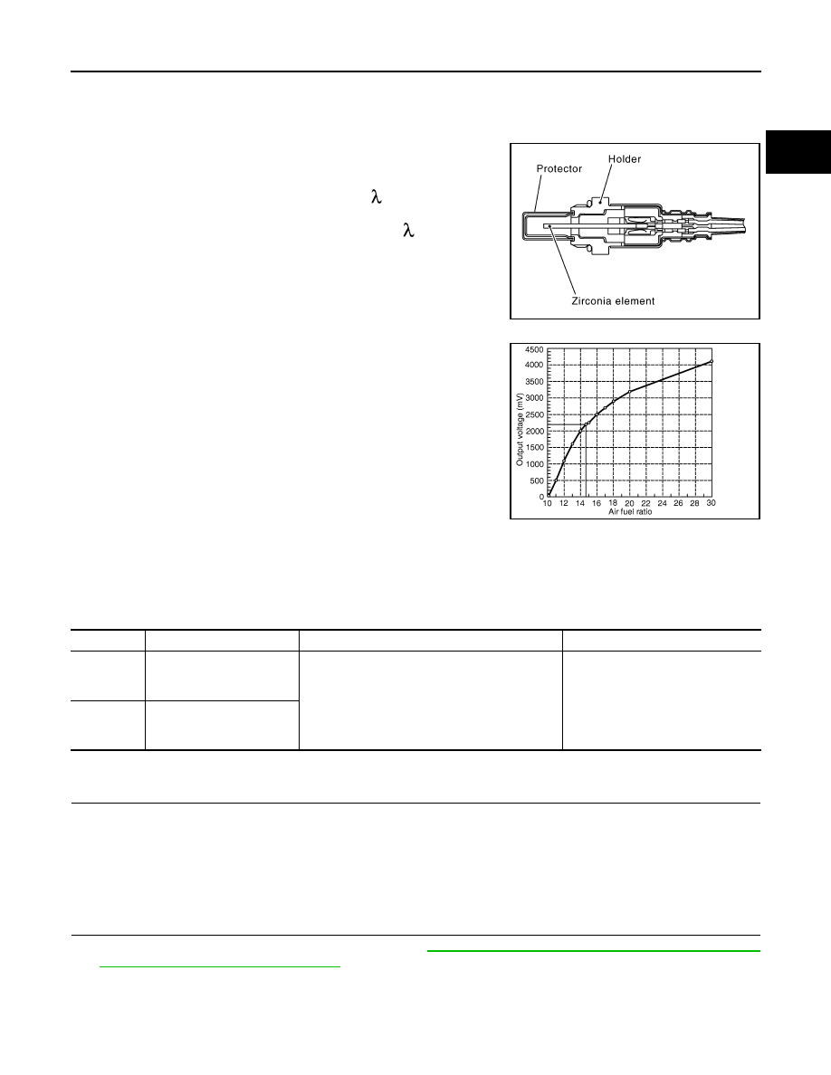
The air fuel ratio (A/F) sensor 1 is a planar one-cell limit current sen-
sor. The sensor element of the A/F sensor 1 is composed an elec-
trode layer, which transports ions. It has a heater in the element.
The sensor is capable of precise measurement = 1, but also in the
lean and rich range. Together with its control electronics, the sensor
outputs a clear, continuous signal throughout a wide range.
The exhaust gas components diffuse through the diffusion layer at
the sensor cell. An electrode layer is applied voltage, and this current
relative oxygen density in lean. Also this current relative hydrocar-
bon density in rich.
Therefore, the A/F sensor 1 is able to indicate air fuel ratio by this
electrode layer of current. In addition, a heater is integrated in the
sensor to ensure the required operating temperature of about 800
°
C
(1,472
°
F).
DTC Logic
INFOID:0000000003133615
DTC DETECTION LOGIC
To judge the malfunction, the A/F signal computed by ECM from the A/F sensor 1 signal is monitored not to be
shifted to LEAN side or RICH side.
DTC CONFIRMATION PROCEDURE
1.
PRECONDITIONING
If DTC Confirmation Procedure has been previously conducted, always turn ignition switch OFF and wait at
least 10 seconds before conducting the next test.
TESTING CONDITION:
Before performing the following procedure, confirm that battery voltage is more than 11 V at idle.
>> GO TO 2.
2.
PERFORM DTC CONFIRMATION PROCEDURE
1.
Clear the mixture ratio self-learning value. Refer to
EC-20, "MIXTURE RATIO SELF-LEARNING VALUE
CLEAR : Special Repair Requirement"
.
2.
Turn ignition switch OFF and wait at least 10 seconds.
3.
Start engine and keep the engine speed between 3,500 and 4,000 rpm for 1 minute under no load.
4.
Let engine idle for 1 minute.
5.
Keep engine speed between 2,500 and 3,000 rpm for 20 minutes.
JMBIA0112GB
PBIB3354E
DTC No.
Trouble diagnosis name
DTC detecting condition
Possible cause
P2A00
Air fuel ratio (A/F) sensor 1
(bank 1) circuit range/per-
formance
• The output voltage computed by ECM from the
A/F sensor 1 signal is shifted to the lean side for
a specified period.
• The A/F signal computed by ECM from the A/F
sensor 1 signal is shifted to the rich side for a
specified period.
• A/F sensor 1
• A/F sensor 1 heater
• Fuel pressure
• Fuel injector
• Intake air leaks
P2A03
Air fuel ratio (A/F) sensor 1
(bank 2) circuit range/per-
formance

EC-436
< COMPONENT DIAGNOSIS >
[VQ35HR]
P2A00, P2A03 A/F SENSOR 1
6.
Check 1st trip DTC.
Is 1st trip DTC detected?
YES
>> Go to
NO
>> INSPECTION END
Diagnosis Procedure
INFOID:0000000003133616
1.
CHECK GROUND CONNECTION
1.
Turn ignition switch OFF.
2.
Check ground connection M95. Refer to Ground Inspection in
Is the inspection result normal?
YES
>> GO TO 2.
NO
>> Repair or replace ground connection.
2.
RETIGHTEN A/F SENSOR 1
1.
Loosen and retighten the A/F sensor 1. Refer to
EM-34, "Removal and Installation"
>> GO TO 3.
3.
CHECK FOR INTAKE AIR LEAK
1.
Start engine and run it at idle.
2.
Listen for an intake air leak after the mass air flow sensor.
Is intake air leak detected?
YES
>> Repair or replace malfunctioning part.
NO
>> GO TO 4.
4.
CLEAR THE MIXTURE RATIO SELF-LEARNING VALUE
1.
Clear the mixture ratio self-learning value. Refer to
EC-20, "MIXTURE RATIO SELF-LEARNING VALUE
CLEAR : Special Repair Requirement"
.
2.
Run engine for at least 10 minutes at idle speed.
Is the 1st trip DTC P0171, P0172, P0174 or P0175 detected? Is it difficult to start engine?
YES
>> Perform trouble diagnosis for DTC P0171, P0174 or P0172, P0175. Refer to
or
NO
>> GO TO 5.
5.
CHECK HARNESS CONNECTOR
1.
Turn ignition switch OFF.
2.
Disconnect A/F sensor 1 harness connector.
3.
Check harness connector for water.
Is the inspection result normal?
YES
>> GO TO 6.
NO
>> Repair or replace harness connector.
6.
CHECK A/F SENSOR 1 POWER SUPPLY CIRCUIT
1.
Turn ignition switch ON.
2.
Check the voltage between A/F sensor 1 harness connector and ground.
Is the inspection result normal?
YES
>> GO TO 8.
Water should not exit.
DTC
A/F sensor 1
Ground
Voltage
Bank
Connector
Terminal
P2A00
1
F3
4
Ground
Battery voltage
P2A03
2
F20
4
P2A00, P2A03 A/F SENSOR 1
EC-437
< COMPONENT DIAGNOSIS >
[VQ35HR]
C
D
E
F
G
H
I
J
K
L
M
A
EC
N
P
O
NO
>> GO TO 7.
7.
DETECT MALFUNCTIONING PART
Check the following.
• Harness connectors E3, F1
• IPDM E/R harness connector E7
• 15A fuse (No. 46)
• Harness for open or short between A/F sensor 1 and fuse
>> Repair or replace harness or connectors.
8.
CHECK A/F SENSOR 1 INPUT SIGNAL CIRCUIT FOR OPEN AND SHORT
1.
Turn ignition switch OFF.
2.
Disconnect ECM harness connector.
3.
Check the continuity between A/F sensor 1 harness connector and ECM harness connector.
4.
Check the continuity between A/F sensor 1 harness connector or ECM harness connector and ground.
5.
Also check harness for short to power.
Is the inspection result normal?
YES
>> GO TO 9.
NO
>> Repair open circuit or short to ground or short to power in harness or connectors.
9.
CHECK A/F SENSOR 1 HEATER
EC-147, "Component Inspection"
Is the inspection result normal?
YES
>> GO TO 10.
NO
>> GO TO 11.
10.
CHECK INTERMITTENT INCIDENT
Perform
GI-38, "Intermittent Incident"
.
Is the inspection result normal?
YES
>> GO TO 11.
NO
>> Repair or replace malfunctioning part.
11.
REPLACE AIR FUEL RATIO (A/F) SENSOR 1
Replace air fuel ratio (A/F) sensor 1.
CAUTION:
• Discard any A/F sensor which has been dropped from a height of more than 0.5 m (19.7 in) onto a
hard surface such as a concrete floor; use a new one.
DTC
A/F sensor 1
ECM
Continuity
Bank
Connector
Terminal
Connector
Terminal
P2A00
1
F3
1
F102
57
Existed
2
61
P2A03
2
F20
1
65
2
66
DTC
A/F sensor 1
ECM
Ground
Continuity
Bank
Connector
Terminal
Connector
Terminal
P2A00
1
F3
1
F102
57
Ground
Not existed
2
61
P2A03
2
F20
1
65
2
66
Нет комментариевНе стесняйтесь поделиться с нами вашим ценным мнением.
Текст