Infiniti EX35. Manual — part 60
AV
AUDIO SYSTEM
AV-21
< FUNCTION DIAGNOSIS >
[BASE AUDIO WITHOUT NAVIGATION]
C
D
E
F
G
H
I
J
K
L
M
B
A
O
P
AUDIO SYSTEM
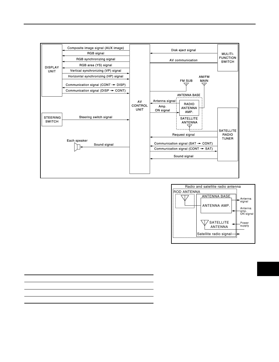
System Diagram
INFOID:0000000003508367
NOTE:
A radio antenna base integrated with radio antenna and satellite
radio antenna is adopted.
System Description
INFOID:0000000003508368
The audio system is equipped with the following functions. Each function can be operated by multifunction
switch, preset switch or steering switch. It indicates the operation status of AUDIO to display.
FUNCTION DESCRIPTION
Operating signal
Operation of the audio system can be performed with multifunction switch, preset switch or steering switch.
• Operating signal is transmitted to AV control unit with AV communication when it is operated by multifunction
switch or preset switch. The disk ejection operating signal is performed by hardwire.
• Operating signal is transmitted to AV control unit with steering switch signal when it is operated by steering
switch.
JSNIA0697GB
JSNIA1062GB
Function
AM/FM radio
Satellite radio
CD
AV-22
< FUNCTION DIAGNOSIS >
[BASE AUDIO WITHOUT NAVIGATION]
AUDIO SYSTEM
Screen display
• The display is switched by communication signal between display and AV control unit.
• The image signal to display operating condition is performed by the RGB signal, RGB area signal and RGB
image synchronizing signal.
AM/FM Radio Mode
• AM/FM radio tuner is built into AV control unit.
• Audio signal is received by rod antenna, next it is amplified by antenna amp., and finally it is input into AV
control unit. The FM sub antenna is installed on the back door window glass and AV control unit receives
audio signal.
• AV control unit outputs the audio signal to each speaker.
Satellite Radio System
• Satellite radio tuner is controlled by communication signal and request signal with AV control unit.
• Satellite radio wave is received by satellite radio antenna and it is input to satellite radio tuner. Satellite radio
tuner outputs satellite radio sound signal to AV control unit.
• AV control unit outputs satellite radio sound signal to each speaker.
CD Mode
• CD function is built into AV control unit.
• AV control unit outputs audio signals to each speaker when CD inserted into AV control unit.
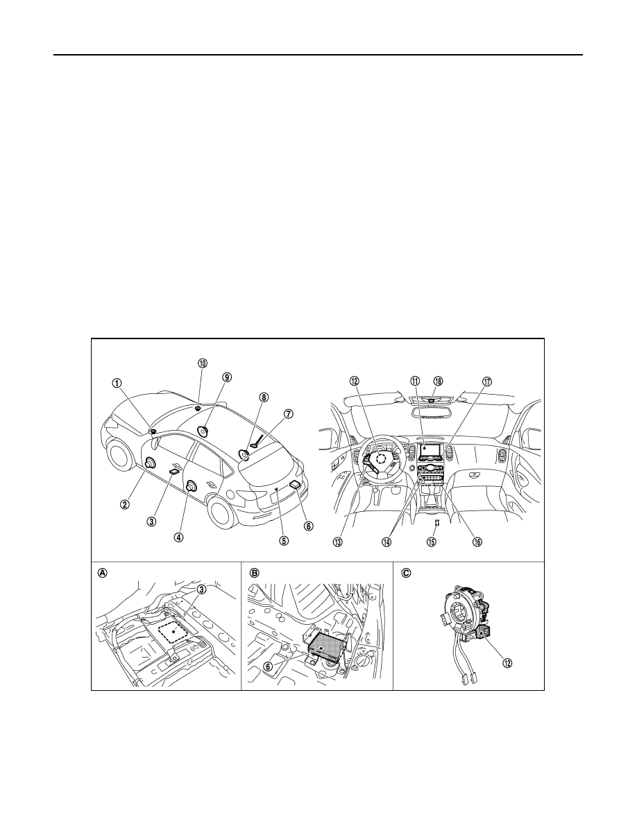
Component Parts Location
INFOID:0000000003579810
1.
Front squawker LH
2.
Front door speaker LH
3.
Camera control unit
4.
Rear door speaker LH
5.
Rear view camera
6.
Satellite radio tuner
7.
Antenna base (antenna amp and sat-
ellite antenna)
8.
Rear door speaker RH
9.
Front door speaker RH
10. Front squawker RH
11. Display unit
12. Steering angle sensor
13. Steering switch
14. Preset switch
15. Auxiliary input jacks
JPNIA0909ZZ

AV
AUDIO SYSTEM
AV-23
< FUNCTION DIAGNOSIS >
[BASE AUDIO WITHOUT NAVIGATION]
C
D
E
F
G
H
I
J
K
L
M
B
A
O
P
Component Description
INFOID:0000000003508370
16. AV control unit
17. Multifunction switch
18. Microphone
A.
Under front seat (LH side)
B.
Luggage floor (RH side)
C.
Spiral cable part
Part name
Description
AV CONTROL UNIT
• The AM/FM receiving function and the CD playing function are equipped.
• Outputs the audio signal to each speaker.
DISPLAY UNIT
• Display image is controlled by the serial communication from AV control unit.
• RGB image signal (audio operation condition) is input from AV control unit.
FRONT DOOR SPEAKER
• Outputs sound signal from AV control unit.
• Outputs sound (mid and low range).
REAR DOOR SPEAKER
• Outputs sound signal from AV control unit.
• Outputs sound (mid and low range).
FRONT SQUAWKER
• Outputs sound signal from AV control unit.
• Outputs sound (high and mid range).
MULTIFUNCTION SWITCH
• Each audio operation can be operated.
• Connected with preset switch via cable, and operation signal is transmitted to
AV control unit via AV communication.
PRESET SWITCH
• Each audio and air conditioner operation can be operated.
• Connected with multifunction switch via cable, and operation signal is transmit-
ted to AV control unit via AV communication.
• The disk ejection operating signal is performed by hardwire
STEERING SWITCH
• Each audio operation can be operated.
• Steering switch signal (operation signal) is output to AV control unit.
ANTENNA BASE
A radio antenna base integrated with radio antenna amp. and satellite radio an-
tenna is adopted.
ANTENNA AMP
• Radio signal received by rod antenna is amplified and transmitted to AV control
unit.
• Power (antenna amp. ON signal) is supplied from AV control unit.
SATELLITE RADIO ANTENNA
• Receives the satellite radio waves and outputs it to satellite radio tuner.
SATELLITE RADIO TUNER
• Inputs the satellite radio signal from satellite radio antenna and outputs the
sound signal to AV control unit.
• It is controlled with AV control unit and serial communication (communication
signal and request signal).
AV-24
< FUNCTION DIAGNOSIS >
[BASE AUDIO WITHOUT NAVIGATION]
REAR VIEW MONITOR SYSTEM
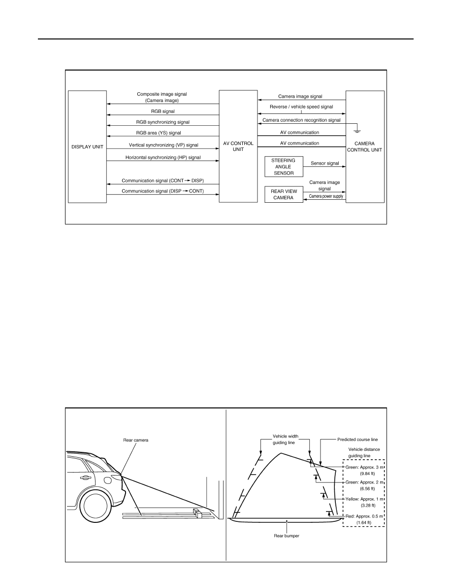
REAR VIEW MONITOR SYSTEM
System Diagram
INFOID:0000000003160905
System Description
INFOID:0000000003533916
CAMERA IMAGE OPERATION PRINCIPLE
• Power is supplied to rear view camera from camera control unit and the rear view camera outputs the cam-
era image to camera control unit when selector lever is set to reverse position and the reverse signal on
camera control unit is input.
• Camera control unit superimposes the guiding line and predicted course line to the image from rear view
camera and outputs to display unit. In this case, the reverse signal is also input to AV control unit. Therefore,
AV control unit recognizes the selector lever as in the reverse position. And then AV control unit switches the
image displayed by the communication signal between AV control unit and display unit with the camera
image.
• AV control unit outputs camera image signal that is inputted from camera control unit to display unit.
• Camera control unit controls the direction and distance of predicted course line according to the sensor sig-
nal from steering angle sensor.
• AV control unit determines whether rear view camera is equipped or not, based on the presence of camera
connection recognition signal. It switches to rear view monitor image at the time of reverse signal input when
rear view camera is equipped.
• Warning message under the rear view monitor display is described by AV control unit.
Rear view monitor guiding line
JSNIA0698GB
JSNIA0707GB
Нет комментариевНе стесняйтесь поделиться с нами вашим ценным мнением.
Текст