Infiniti EX35. Manual — part 1141
PCS
PUSH-BUTTON IGNITION SWITCH
PCS-65
< COMPONENT DIAGNOSIS >
[POWER DISTRIBUTION SYSTEM]
C
D
E
F
G
H
I
J
K
L
B
A
O
P
N
PUSH-BUTTON IGNITION SWITCH
Description
INFOID:0000000003657684
BCM transmits the change in the power supply position with the push-button ignition switch to IPDM E/R via
the CAN communication line. IPDM E/R transmits the power supply position status via CAN communication
line to BCM.
Component Function Check
INFOID:0000000003657685
1.
CHECK FUNCTION
1.
Select “PUSH SW” in “Data Monitor” mode with CONSULT-III.
2.
Check the push-button ignition switch signal under the following condition.
Is the indication normal?
YES
>> INSPECTION END
NO
Diagnosis Procedure
INFOID:0000000003657686
1.
CHECK PUSH-BUTTON IGNITION SWITCH OPERATION
Press push-button ignition switch and check if it turns to ON.
Does ignition switch turn to ON?
YES
>> GO TO 2.
NO
>> GO TO 4.
2.
CHECK IGNITION SWITCH OUTPUT SIGNAL (IPDM E/R)
1.
Disconnect push-button ignition switch connector.
2.
Check voltage between IPDM E/R harness connector and ground.
Is the inspection result normal?
YES
>> GO TO 3.
NO
>> Replace IPDM E/R. Refer to
PCS-34, "Removal and Installation"
.
3.
CHECK PUSH-BUTTON IGNITION SWITCH CIRCUIT (IPDM E/R)
1.
Disconnect IPDM E/R connector and BCM connector.
2.
Check continuity between IPDM E/R harness connector and push-button ignition switch harness connec-
tor.
3.
Check continuity between IPDM E/R harness connector and ground.
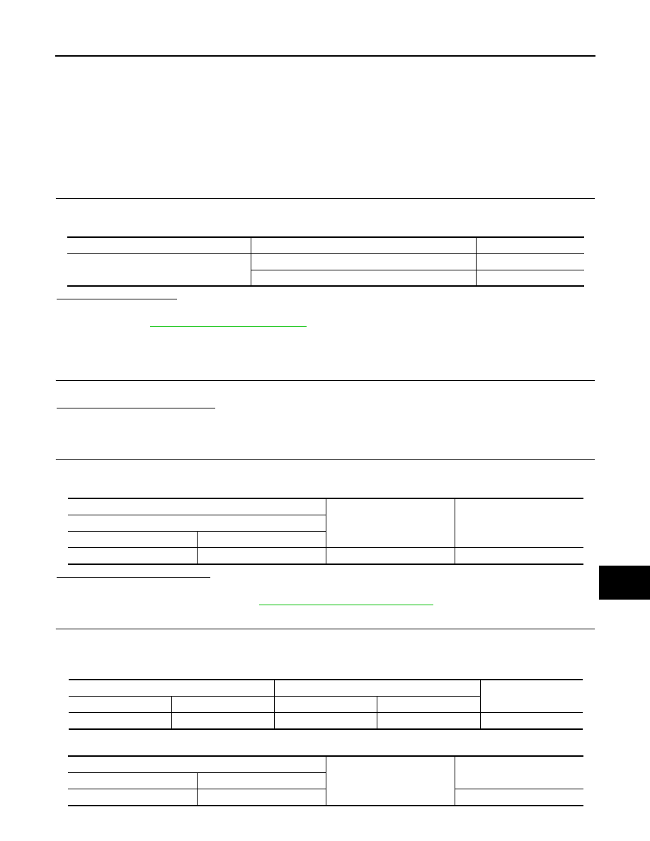
Test item
Condition
Status
PUSH SW
Push-button ignition switch is pressed
ON
Push-button ignition switch is not pressed
OFF
(+)
(–)
Voltage (V)
(Approx.)
IPDM E/R
Connector
Terminal
E5
28
Ground
Battery voltage
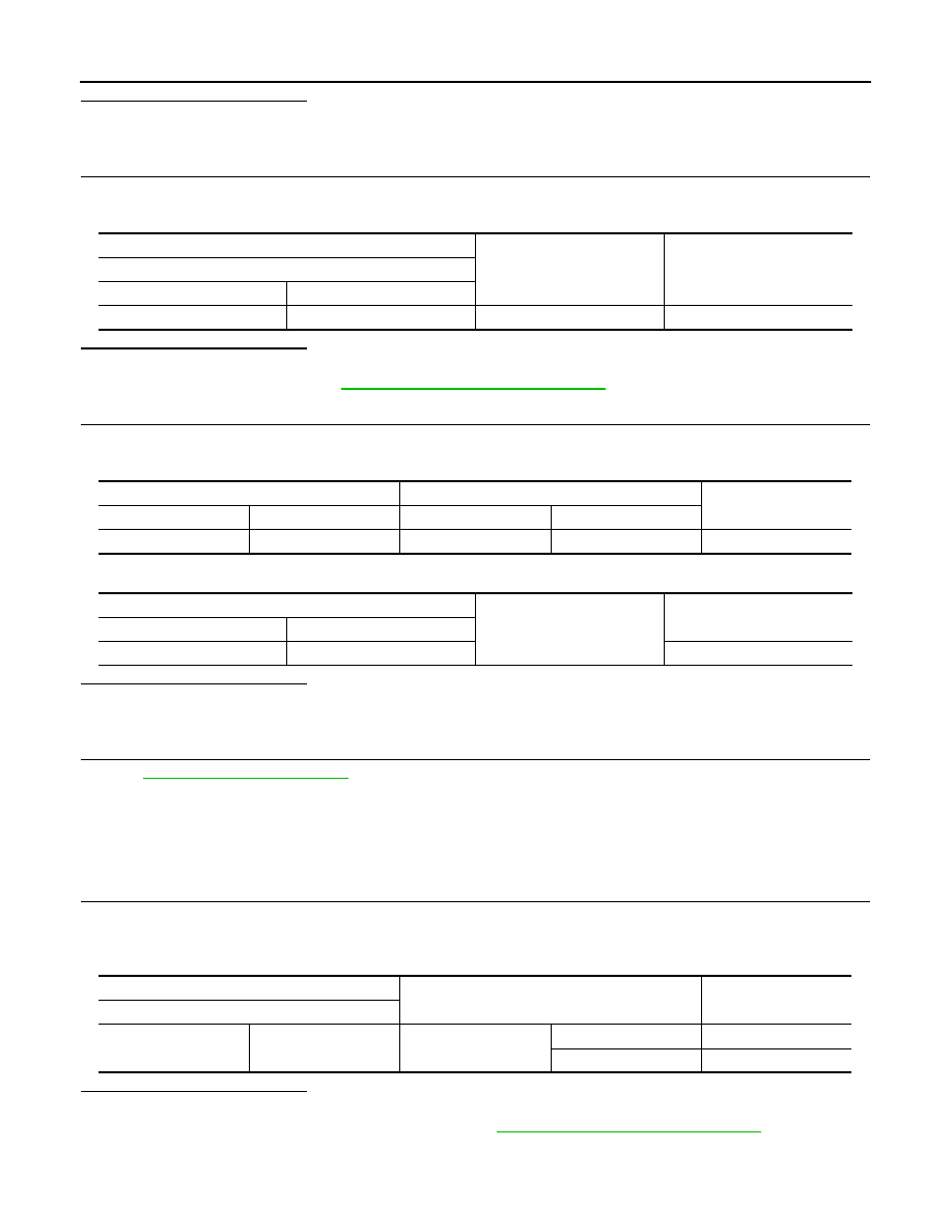
IPDM E/R
Push-button ignition switch
Continuity
Connector
Terminal
Connector
Terminal
E5
28
M50
4
Existed
IPDM E/R
Ground
Continuity
Connector
Terminal
E5
28
Not existed
PCS-66
< COMPONENT DIAGNOSIS >
[POWER DISTRIBUTION SYSTEM]
PUSH-BUTTON IGNITION SWITCH
Is the inspection result normal?
YES
>> GO TO 6.
NO
>> Repair or replace harness or connector.
4.
CHECK IGNITION SWITCH OUTPUT SIGNAL (BCM)
1.
Disconnect push-button ignition switch connector.
2.
Check voltage between BCM harness connector and ground.
Is the inspection result normal?
YES
>> GO TO 5.
NO
>> Replace BCM. Refer to
PCS-130, "Removal and Installation"
.
5.
CHECK PUSH-BUTTON IGNITION SWITCH CIRCUIT (BCM)
1.
Disconnect BCM connector and IPDM E/R connector.
2.
Check continuity between BCM harness connector and push-button ignition switch harness connector.
3.
Check continuity between BCM harness connector and ground.
Is the inspection result normal?
YES
>> GO TO 6.
NO
>> Repair or replace harness or connector.
6.
CHECK INTERMITTENT INCIDENT
GI-38, "Intermittent Incident"
>> INSPECTION END
Component Inspection
INFOID:0000000003657687
1.
CHECK PUSH-BUTTON IGNITION SWITCH
1.
Turn ignition switch OFF.
2.
Disconnect push-button ignition switch connector.
3.
Check continuity between push-button ignition switch terminals.
Is the inspection result normal?
YES
>> INSPECTION END.
NO
>> Replace push-button ignition switch. Refer to
PCS-131, "Removal and Installation"
.
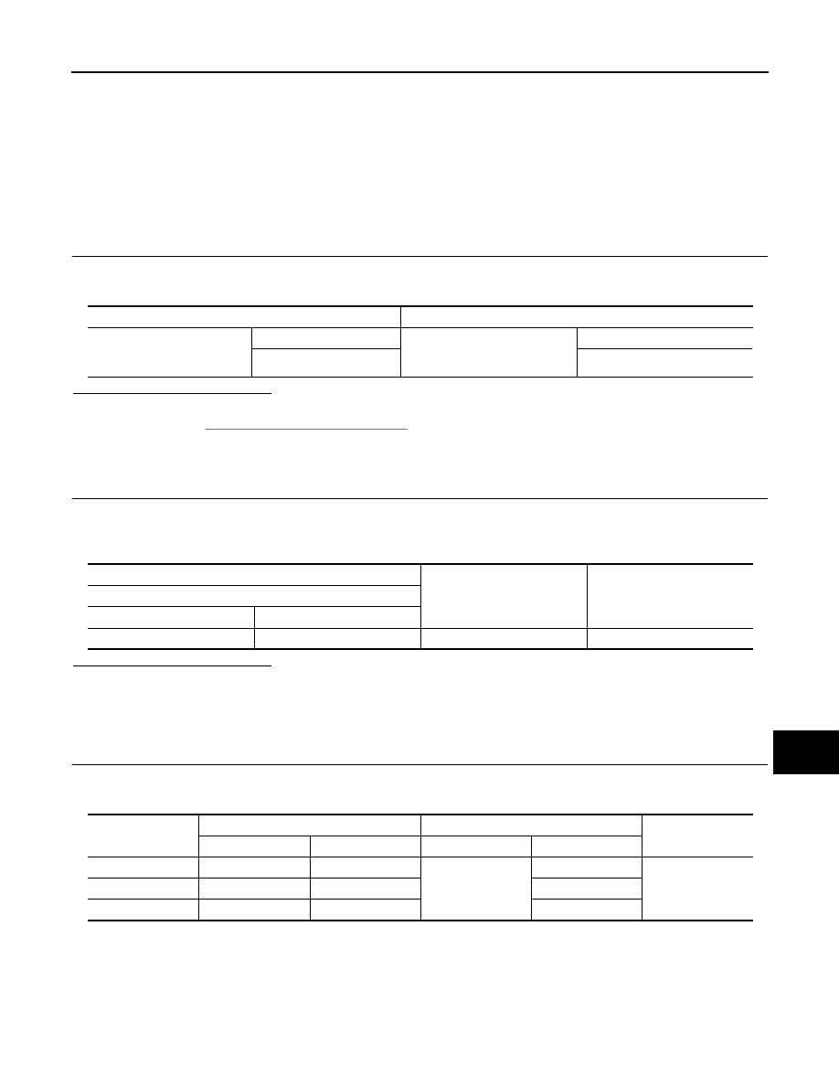
(+)
(–)
Voltage (V)
(Approx.)
BCM
Connector
Terminal
M122
89
Ground
Battery voltage
BCM
Push-button ignition switch
Continuity
Connector
Terminal
Connector
Terminal
M122
89
M50
4
Existed
BCM
Ground
Continuity
Connector
Terminal
M122
89
Not existed
Push-button ignition switch
Condition
Continuity
Terminal
1
4
Push-button ignition
switch
Pressed
Existed
Not pressed
Not existed
PCS
PUSH-BUTTON IGNITION SWITCH POSITION INDICATOR
PCS-67
< COMPONENT DIAGNOSIS >
[POWER DISTRIBUTION SYSTEM]
C
D
E
F
G
H
I
J
K
L
B
A
O
P
N
PUSH-BUTTON IGNITION SWITCH POSITION INDICATOR
Description
INFOID:0000000003657688
The switch that changes the power supply position.
BCM maintains the power supply position status.
BCM changes the power supply position with the operation of the push-button ignition switch.
Component Function Check
INFOID:0000000003657689
1.
CHECK FUNCTION
Check push-button ignition switch (“LOCK INDICATOR”, “ACC INDICATOR” and “IGNITION ON IND”) in
Active Test Mode with CONSULT-III.
Is the inspection result normal?
YES
>> INSPECTION END
NO
>> Refer to
Diagnosis Procedure
INFOID:0000000003657690
1.
CHECK PUSH-BUTTON IGNITION SWITCH INPUT SIGNAL
1.
Turn ignition switch OFF.
2.
Disconnect push-button ignition switch connector.
3.
Check voltage between push-button ignition switch harness connector and ground.
Is the inspection result normal?
YES
>> GO TO 2.
NO
>>
Check the following.
• 10A fuse [No.9, located in fuse block (J/B)]
• Harness for open or short between push-button ignition switch and fuse
2.
CHECK PUSH-BUTTON IGNITION SWITCH CIRCUIT
1.
Disconnect BCM connector and push button ignition switch connector.
2.
Check continuity between BCM harness connector and push-button ignition switch harness connector.
3.
Check continuity between BCM harness connector and ground.
Test item
Description
LOCK INDICATOR
ACC INDICATOR
IGNITION ON IND
ON
Position indicator
Illuminate
OFF
Not illuminate
(+)
(–)
Voltage (V)
(Approx.)
Push-button ignition switch
Connector
Terminal
M50
8
Ground
Battery voltage
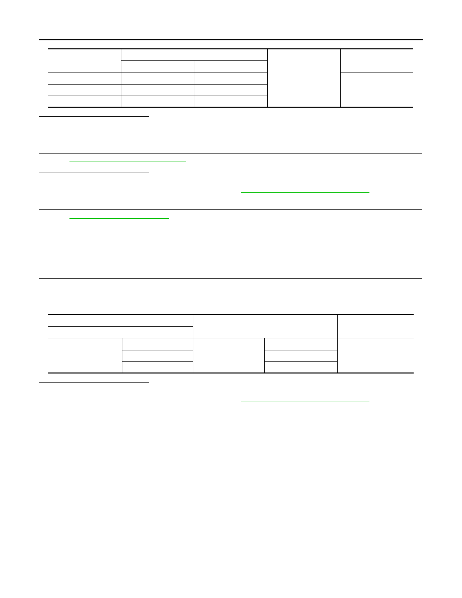
Indicator
BCM
Push-button ignition switch
Continuity
Connector
Terminal
Connector
Terminal
LOCK position
M123
134
M50
5
Existed
ACC position
M119
15
6
ON position
M122
93
7
PCS-68
< COMPONENT DIAGNOSIS >
[POWER DISTRIBUTION SYSTEM]
PUSH-BUTTON IGNITION SWITCH POSITION INDICATOR
Is the inspection result normal?
YES
>> GO TO 3.
NO
>> Repair or replace harness or connector.
3.
CHECK PUSH-BUTTON IGNITION SWITCH
PCS-68, "Component Inspection"
.
Is the inspection result normal?
YES
>> GO TO 4.
NO
>> Replace push-button ignition switch. Refer to
PCS-131, "Removal and Installation"
.
4.
CHECK INTERMITTENT INCIDENT
GI-38, "Intermittent Incident"
>> INSPECTION END
Component Inspection
INFOID:0000000003657691
1.
CHECK PUSH-BUTTON IGNITION SWITCH
1.
Turn ignition switch OFF.
2.
Disconnect push-button ignition switch connector.
3.
Check continuity between push-button ignition switch terminals.
Is the inspection result normal?
YES
>> INSPECTION END
NO
>> Replace push-button ignition switch. Refer to
PCS-131, "Removal and Installation"
.
Indicator
BCM
Ground
Continuity
Connector
Terminal
LOCK position
M123
134
Not existed
ACC position
M119
15
ON position
M122
93
Terminal
Condition
Continuity
Push-button ignition switch
8
5
Push-button ignition
switch position
LOCK
Existed
6
ACC
7
ON
Нет комментариевНе стесняйтесь поделиться с нами вашим ценным мнением.
Текст