Infiniti EX35. Manual — part 848
FAX-22
< ON-VEHICLE REPAIR >
[AWD]
FRONT DRIVE SHAFT BOOT
• Check that anticorrosive oil is applied to the thread of the drive shaft. If not, apply appropriate oil
such as engine oil.
• If sufficient oil is not applied to the thread of the drive shaft, the hub lock nut may be seized and
the tightening torque reaches the specified limit prematurely. It may cause looseness or abnor-
mal noises.
14. Install steering knuckle. Refer to
.
15. Install steering outer socket to steering knuckle. Refer to
16. Tighten the hub lock nut to the specified torque, and install cotter pin. Refer to
CAUTION:
• Never reuse cotter pin.
• Bend it at the root sufficiently to prevent any looseness.
17. Install disc rotor. Refer to
BR-35, "BRAKE CALIPER ASSEMBLY : Removal and Installation"
18. Install caliper assembly to steering knuckle. Refer to
BR-34, "BRAKE CALIPER ASSEMBLY : Exploded
.
19. Install brake hose bracket to steering knuckle. Refer to
BR-20, "FRONT : Exploded View"
.
20. Install wheel sensor to steering knuckle. Refer to
BRC-107, "FRONT WHEEL SENSOR : Exploded View"
.
FINAL DRIVE SIDE
FINAL DRIVE SIDE : Removal and Installation
INFOID:0000000003573812
NOTE:
Remove boot after removing drive shaft. Refer to
FAX-24, "LEFT SIDE : Removal and Installation"
(left side),
FAX-24, "RIGHT SIDE : Removal and Installation"
(right side).
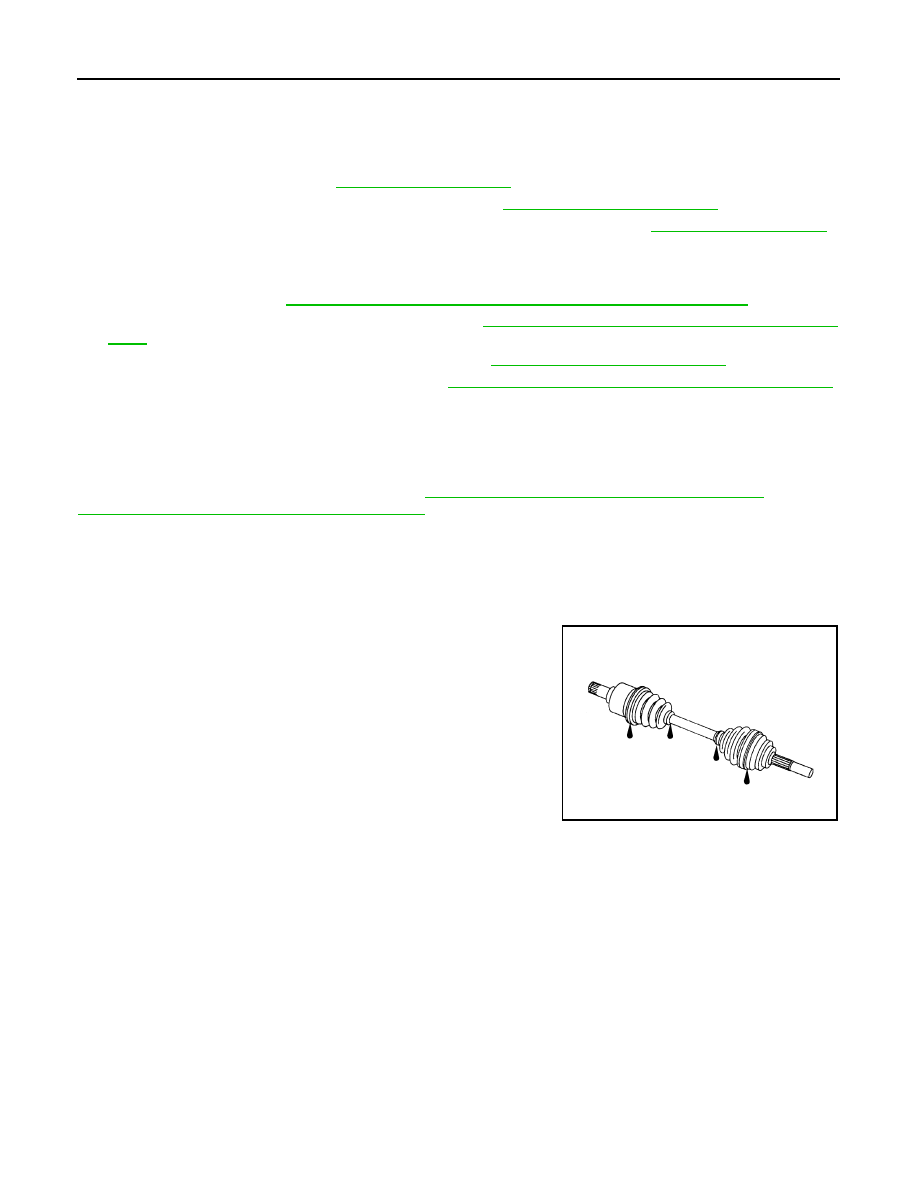
Inspection
INFOID:0000000003573826
INSPECTION AFTER REMOVAL
• Move joint up/down, left/right, and in the axial directions. Check for motion that is not smooth and for signifi-
cant looseness.
• Check boot for cracks, damage, and leakage of grease.
• Disassemble drive shaft and exchange malfunctioning part if there
is a non-standard condition.
SDIA1163J
FRONT DRIVE SHAFT
FAX-23
< ON-VEHICLE REPAIR >
[AWD]
C
E
F
G
H
I
J
K
L
M
A
B
FAX
N
O
P
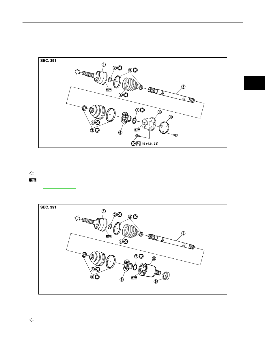
FRONT DRIVE SHAFT
Exploded View
INFOID:0000000003138943
LEFT SIDE
RIGHT SIDE
1.
Joint sub-assembly
2.
Circular clip
3.
Boot band
4.
Boot
5.
Shaft
6.
Spider assembly
7.
Snap ring
8.
Housing
9.
Plug
: Wheel side
: NISSAN genuine grease or an equivalent.
Refer to
for symbols not described on the above.
JPDIF0168GB
1.
Joint sub-assembly
2.
Circular clip
3.
Boot band
4.
Boot
5.
Shaft
6.
Spider assembly
7.
Snap ring
8.
Housing
9.
Dust shield
: Wheel side
JPDIF0169ZZ
FAX-24
< ON-VEHICLE REPAIR >
[AWD]
FRONT DRIVE SHAFT
LEFT SIDE
LEFT SIDE : Removal and Installation
INFOID:0000000003138944
REMOVAL
1.
Remove tires with power tool.
2.
Remove wheel sensor and sensor harness. Refer to
BRC-107, "FRONT WHEEL SENSOR : Exploded
.
CAUTION:
Never pull on wheel sensor harness.
3.
Remove brake hose bracket. Refer to
BR-20, "FRONT : Exploded View"
.
4.
Remove caliper assembly mounting bolts with power tool. Hang caliper assembly in a place where it will
not interfere with work. Refer to
BR-34, "BRAKE CALIPER ASSEMBLY : Exploded View"
.
CAUTION:
Never depress brake pedal while brake caliper is removed.
5.
Remove disc rotor. Refer to
BR-35, "BRAKE CALIPER ASSEMBLY : Removal and Installation"
.
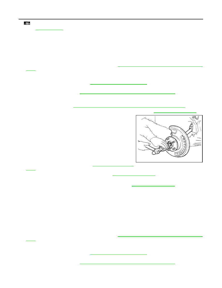
6.
Remove cotter pin, and then loosen hub lock nut with a power tool. Refer to
7.
Patch hub lock nut with a piece of wood. Hammer the wood to
disengage wheel hub and bearing assembly from drive shaft.
CAUTION:
• Never place drive shaft joint at an extreme angle. Also be
careful not to overextend slide joint.
• Never allow drive shaft to hang down without support for
joint sub-assembly, shaft and the other parts.
NOTE:
Use suitable puller if wheel hub and drive shaft cannot be sepa-
rated even after performing the above procedure.
8.
Remove wheel hub lock nut.
9.
Remove steering outer socket. Refer to
.
10. Separate upper link from steering knuckle. Refer to
.
11. Remove drive shaft from wheel hub and bearing assembly.
12. Remove shock absorber from vehicle with power tool. Refer to
13. Remove mounting bolts, and then remove drive shaft from vehicle.
INSTALLATION
Install in the reverse order of removal.
RIGHT SIDE
RIGHT SIDE : Removal and Installation
INFOID:0000000003759868
REMOVAL
1.
Remove tires with power tool.
2.
Remove wheel sensor and sensor harness. Refer to
BRC-107, "FRONT WHEEL SENSOR : Exploded
.
CAUTION:
Never pull on wheel sensor harness.
3.
Remove brake hose bracket. Refer to
BR-20, "FRONT : Exploded View"
.
4.
Remove caliper assembly mounting bolts with power tool. Hang caliper assembly in a place where it will
not interfere with work. Refer to
BR-34, "BRAKE CALIPER ASSEMBLY : Exploded View"
.
CAUTION:
Never depress brake pedal while brake caliper is removed.
: NISSAN genuine grease or an equivalent.
Refer to
for symbols not described on the above.
JPDIG0070ZZ
FRONT DRIVE SHAFT
FAX-25
< ON-VEHICLE REPAIR >
[AWD]
C
E
F
G
H
I
J
K
L
M
A
B
FAX
N
O
P
5.
Remove disc rotor. Refer to
BR-35, "BRAKE CALIPER ASSEMBLY : Removal and Installation"
.
6.
Remove cotter pin, and then loosen hub lock nut with a power tool.
7.
Patch hub lock nut with a piece of wood. Hammer the wood to
disengage wheel hub and bearing assembly from drive shaft.
CAUTION:
• Never place drive shaft joint at an extreme angle. Also be
careful not to overextend slide joint.
• Never allow drive shaft to hang down without support for
joint sub-assembly, shaft and the other parts.
NOTE:
Use suitable puller if wheel hub and drive shaft cannot be sepa-
rated even after performing the above procedure.
8.
Remove wheel hub lock nut.
9.
Remove steering outer socket. Refer to
.
10. Separate upper link from vehicle. Refer to
11. Remove drive shaft from wheel hub and bearing assembly.
12. Remove shock absorber from transverse link with power tool. Refer to
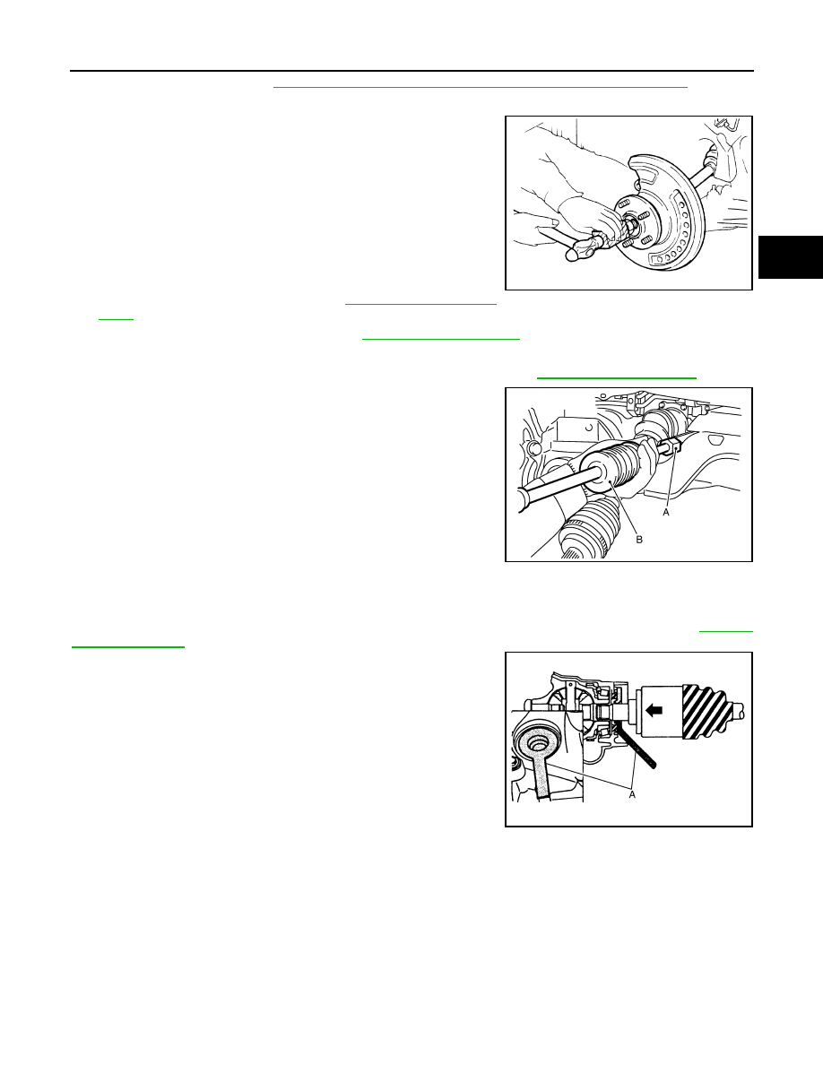
13. Remove drive shaft from front final drive using the drive shaft
attachment (A) [SST:KV40107500 (
−
)] and a sliding ham-
mer (B) while inserting tip of the drive shaft attachment between
housing and front final drive.
CAUTION:
Never place drive shaft joint at an extreme angle when
removing drive shaft. Also be careful not to overextend
slide joint.
INSTALLATION
Note the following, and install in the reverse order of removal.
CAUTION:
Always replace final drive oil seal with new one when installing drive shaft. Refer to
• Place the protector (A) [SST:KV38107900 (
−
)] onto final drive
to prevent damage to the oil seal while inserting drive shaft. Slide
drive shaft sliding joint and tap with a hammer to install securely.
WHEEL SIDE
WHEEL SIDE : Disassembly and Assembly
INFOID:0000000003573813
DISASSEMBLY
1.
Fix shaft with a vise.
CAUTION:
Protect shaft when fixing with a vise using aluminum or copper plates.
2.
Remove boot bands, and then remove boot from joint sub-assembly.
JPDIG0070ZZ
JPDIF0004ZZ
JPDIF0023ZZ
Нет комментариевНе стесняйтесь поделиться с нами вашим ценным мнением.
Текст