Infiniti EX35. Manual — part 847
FAX-18
< ON-VEHICLE REPAIR >
[AWD]
FRONT DRIVE SHAFT BOOT
FRONT DRIVE SHAFT BOOT
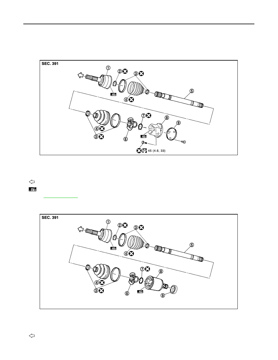
Exploded View
INFOID:0000000003138941
LEFT SIDE
RIGHT SIDE
1.
Joint sub-assembly
2.
Circular clip
3.
Boot band
4.
Boot
5.
Shaft
6.
Spider assembly
7.
Snap ring
8.
Housing
9.
Plug
: Wheel side
: NISSAN genuine grease or an equivalent.
for symbols not described on the above.
JPDIF0168GB
1.
Joint sub-assembly
2.
Circular clip
3.
Boot band
4.
Boot
5.
Shaft
6.
Spider assembly
7.
Snap ring
8.
Housing
9.
Dust shield
: Wheel side
JPDIF0169ZZ
FRONT DRIVE SHAFT BOOT
FAX-19
< ON-VEHICLE REPAIR >
[AWD]
C
E
F
G
H
I
J
K
L
M
A
B
FAX
N
O
P
WHEEL SIDE
WHEEL SIDE : Removal and Installation
INFOID:0000000003573811
REMOVAL
1.
Remove tires with power tool.
2.
Remove wheel sensor and sensor harness. Refer to
BRC-107, "FRONT WHEEL SENSOR : Exploded
.
CAUTION:
Never pull on wheel sensor harness.
3.
Remove brake hose bracket. Refer to
BR-20, "FRONT : Exploded View"
.
4.
Remove caliper assembly mounting bolts with power tool. Hang caliper assembly in a place where it will
not interfere with work. Refer to
BR-34, "BRAKE CALIPER ASSEMBLY : Exploded View"
.
CAUTION:
Never depress brake pedal while brake caliper is removed.
5.
Remove disc rotor. Refer to
BR-35, "BRAKE CALIPER ASSEMBLY : Removal and Installation"
.
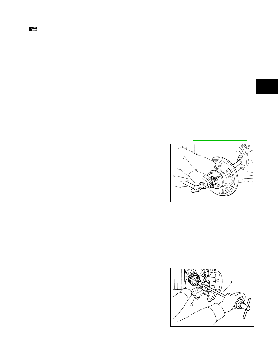
6.
Remove cotter pin, and then loosen hub lock nut with a power tool. Refer to
7.
Patch hub lock nut with a piece of wood. Hammer the wood to
disengage wheel hub and bearing assembly from drive shaft.
CAUTION:
• Never place drive shaft joint at an extreme angle. Also be
careful not to overextend slide joint.
• Never allow drive shaft to hang down without support for
joint sub-assembly, shaft and the other parts.
NOTE:
Use suitable puller if wheel hub and bearing assembly and drive
shaft cannot be separated even after performing the above pro-
cedure.
8.
Remove wheel hub lock nut.
9.
Remove steering outer socket. Refer to
10. Remove cotter pin of transverse link and steering knuckle, and then loosen nut. Refer to
11. Separate steering knuckle from transverse link so as not to damage ball joint boot using the ball joint
remover.
CAUTION:
Temporarily tighten the nut to prevent damage to threads and to prevent the ball joint remover
from suddenly coming off.
12. Remove drive shaft from wheel hub and bearing assembly.
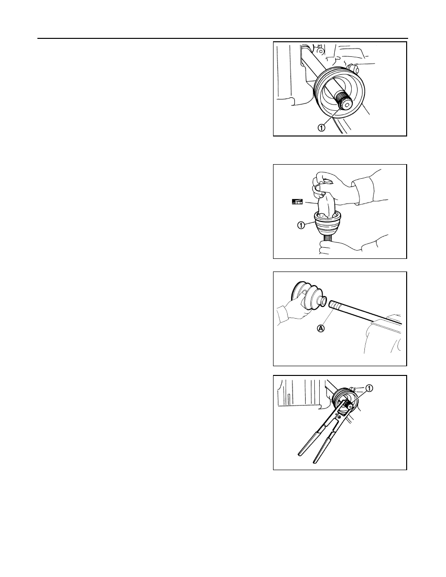
13. Remove boot bands, and then remove boot from joint sub-assembly.
14. Screw drive shaft puller (A) 30 mm (1.18 in) or more into the
thread of joint sub-assembly, and pull joint sub-assembly with a
sliding hammer (B) from shaft.
CAUTION:
• Align a sliding hammer and drive shaft and remove them
by pulling firmly and uniformly.
• If joint sub-assembly cannot be pulled out, try after
removing drive shaft from vehicle.
: NISSAN genuine grease or an equivalent.
Refer to
for symbols not described on the above.
JPDIG0070ZZ
JPDIF0022ZZ
FAX-20
< ON-VEHICLE REPAIR >
[AWD]
FRONT DRIVE SHAFT BOOT
15. Remove circular clip (1) from shaft.
16. Remove boot from shaft.
INSTALLATION
1.
Clean the old grease on joint sub-assembly with paper waste.
2.
Fill serration slot joint sub-assembly (1) with NISSAN genuine
grease or equivalent until the serration slot and ball groove
become full to the brim.
CAUTION:
After applying grease, use a shop cloth to wipe off old
grease that has oozed out.
3.
Wrap serration on shaft with tape (A) to protect the boot from
damage. Install boot and boot bands to shaft.
CAUTION:
Never reuse boot and boot band.
4.
Remove the tape wrapped around the serration on shaft.
5.
Position circular clip (1) on groove at the shaft edge.
CAUTION:
Never reuse circular clip.
NOTE:
Drive joint inserter is recommended when installing circular clip.
6.
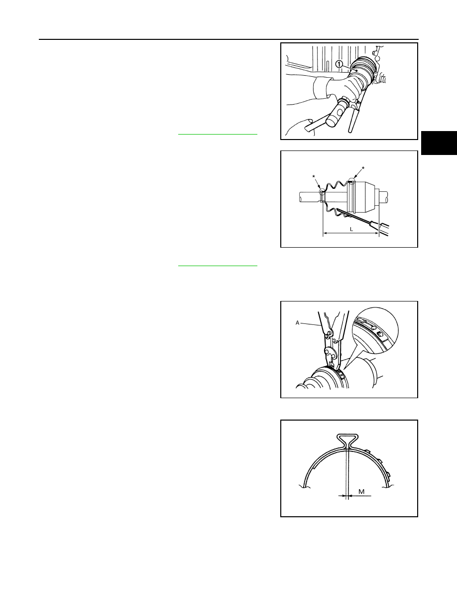
Align both center axles of the shaft edge and joint sub-assembly.
Then assemble shaft with circular clip joint sub-assembly.
JPDIF0007ZZ
JPDIF0008ZZ
JPDIF0009ZZ
JPDIF0010ZZ
FRONT DRIVE SHAFT BOOT
FAX-21
< ON-VEHICLE REPAIR >
[AWD]
C
E
F
G
H
I
J
K
L
M
A
B
FAX
N
O
P
7.
Install joint sub-assembly (1) to shaft using plastic hammer.
CAUTION:
Confirm that joint sub-assembly is correctly engaged while
rotating drive shaft.
8.
Fill serration slot joint sub-assembly with NISSAN genuine
grease or equivalent until the serration slot and ball grove
become full to the brim.
9.
Install the boot securely into grooves (indicated by “*” marks)
shown in the figure.
CAUTION:
If grease adheres to the boot mounting surface (indicated
by “*” mark) on the shaft or joint sub-assembly, boot may
come off. Remove all grease from the surface.
10. To prevent from the deformation of the boot, adjust the boot
installation length (L) to the specified value shown below by
inserting the suitable tool into inside of the boot from the large
diameter side of the boot and discharging the inside air.
CAUTION:
• If the boot mounting length is outside the standard, it may cause breakage in the boot.
• Be careful not to touch the inside of the boot with a tip of tool.
11. Secure the ends of the boot with boot bands using the boot band
crimping tool (A) [SST: KV40107300 (
−
)].
CAUTION:
Never reuse boot band.
NOTE:
Secure boot band so that dimension (M) meets the specification
as shown in the figure.
12. Secure joint sub-assembly and shaft, and then make sure that
they are in the correct position when rotating boot. Install them
with boot band when boot installation positions become incor-
rect.
CAUTION:
Never reuse boot band.
13. Insert drive shaft to wheel hub and bearing assembly, and then
temporarily tighten hub lock nut.
CAUTION:
• The drive shaft is press-fit. When assembling the shaft, never press it, but pull it until fully
seated by tightening the hub lock nut.
Standard
Grease amount
: Refer to
.
JPDIF0011ZZ
Standard
L
: Refer to
.
JPDIF0018ZZ
JPDIF0012ZZ
M
: 2.0 – 3.0 mm (0.079 – 0.118 in)
DSF0047D
Нет комментариевНе стесняйтесь поделиться с нами вашим ценным мнением.
Текст