Infiniti EX35. Manual — part 675
EC-442
< COMPONENT DIAGNOSIS >
[VQ35HR]
ASCD INDICATOR
ASCD INDICATOR
Description
INFOID:0000000003133622
ASCD indicator lamp illuminates to indicate ASCD operation status. Lamp has two indicators, CRUISE and
SET, and is integrated in combination meter.
CRUISE lamp illuminates when MAIN switch on ASCD steering switch is turned ON to indicated that ASCD
system is ready for operation.
SET lamp illuminates when following conditions are met.
• CRUISE lamp is illuminated.
• SET/COAST switch on ASCD steering switch is turned ON while vehicle speed is within the range of ASCD
setting.
SET lamp remains lit during ASCD control.
Refer to
for the ASCD function.
Component Function Check
INFOID:0000000003133623
1.
CHECK ASCD INDICATOR FUNCTION
Check ASCD indicator under the following conditions.
Is the inspection result normal?
YES
>> INSPECTION END
NO
>> Go to
Diagnosis Procedure
INFOID:0000000003133624
1.
CHECK DTC
Check that DTC U1000 or U1001 is not displayed.
Is the inspection result normal?
YES
>> GO TO 2.
NO
>> Perform trouble diagnosis for DTC U1000, U1001. Refer to
2.
CHECK DTC WITH “UNIFIED METER AND A/C AMP.”
MWI-40, "CONSULT-III Function (METER/M&A)"
.
Is the inspection result normal?
YES
>> GO TO 3.
NO
>> Repair or replace malfunctioning part.
3.
CHECK INTERMITTENT INCIDENT
GI-38, "Intermittent Incident"
Is the inspection result normal?
YES
>> Replace combination meter.
NO
>> Repair or replace malfunctioning part.
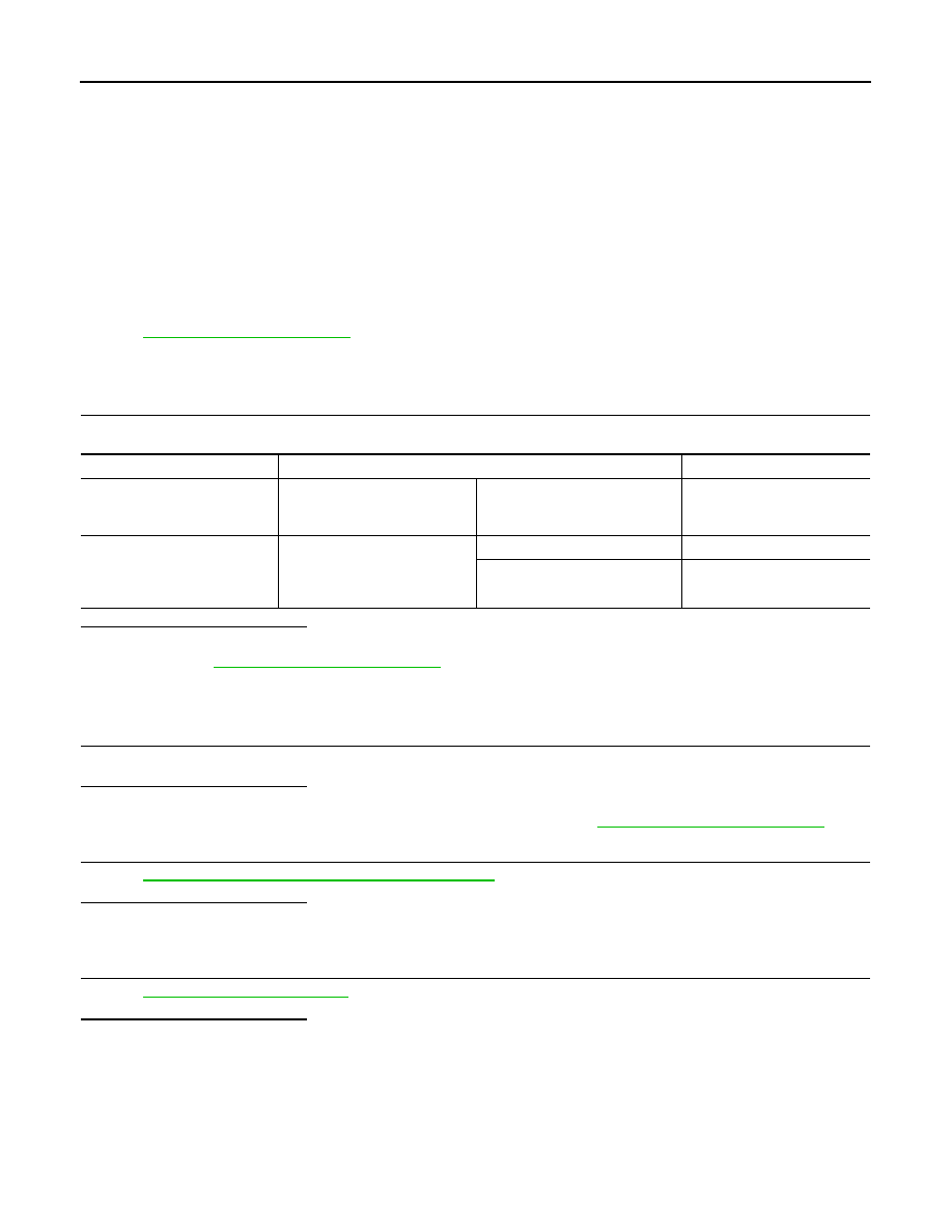
ASCD INDICATOR
CONDITION
SPECIFICATION
CRUISE LAMP
• Ignition switch: ON
• MAIN switch: Pressed at the
1st time
→
at the 2nd time
ON
→
OFF
SET LAMP
• MAIN switch: ON
• When vehicle speed is be-
tween 40 km/h (25 MPH) and
144 km/h (89 MPH)
• ASCD: Operating
ON
• ASCD: Not operating
OFF
COOLING FAN
EC-443
< COMPONENT DIAGNOSIS >
[VQ35HR]
C
D
E
F
G
H
I
J
K
L
M
A
EC
N
P
O
COOLING FAN
Description
INFOID:0000000003133625
COOLING FAN CONTROL MODULE
Cooling fan control module receives ON/OFF pulse duty signal from IPDM E/R. Corresponding to this ON/OFF
pulse duty signal, cooling fan control module sends cooling fan motor operating voltage to cooling fan motor.
The revolution speed of cooling fan motor is controlled by duty cycle of the voltage.
COOLING FAN MOTOR
Cooling fan motor receives cooling fan motor operating voltage from cooling fan control module. The revolu-
tion speed of cooling fan motor is controlled by duty cycle of the voltage.
Component Function Check
INFOID:0000000003133626
1.
CHECK COOLING FAN FUNCTION
With CONSULT-III
1.
Turn ignition switch ON.
2.
Perform “FAN DUTY CONTROL” in “ACTIVE TEST” mode with CONSULT-III.
3.
Check that cooling fan speed varies according to the percent.
Without CONSULT-III
1.
Perform IPDM E/R auto active test and check cooling fan motors operation, refer to
.
2.
Check that cooling fan operates.
Is the inspection result normal?
YES
>> INSPECTION END
NO
>> Go to
Diagnosis Procedure
INFOID:0000000003133627
1.
CHECK COOLING FAN CONTROL MODULE POWER SUPPLY CIRCUIT-I
1.
Turn ignition switch OFF.
2.
Disconnect cooling fan control module harness connector E37.
3.
Turn ignition switch ON.
4.
Check the voltage between cooling fan control module harness connector and ground.
Is the inspection result normal?
YES
>> GO TO 2.
NO
>> GO TO 7.
2.
CHECK COOLING FAN CONTROL MODULE GROUND CIRCUIT
1.
Turn ignition switch OFF.
2.
Check the continuity between cooling fan control module harness connector and ground.
3.
Also check harness for short to power.
Is the inspection result normal?
YES
>> GO TO 3.
NO
>> Repair open circuit or short to power in harness or connectors.
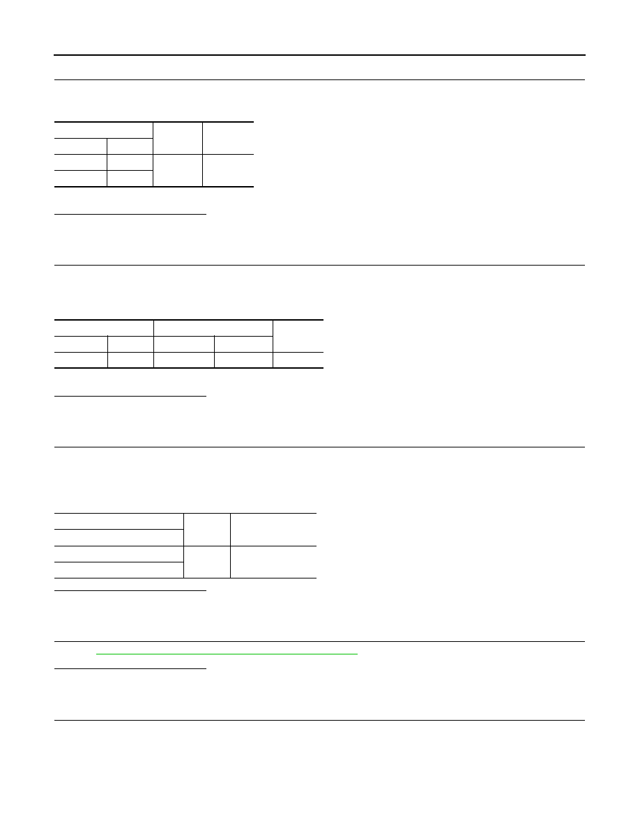
Cooling fan control module
Ground
Voltage
Connector
Terminal
E37
3
Ground
Battery voltage
Cooling fan control module
Ground
Continuity
Connector
Terminal
E37
1
Ground
Existed
EC-444
< COMPONENT DIAGNOSIS >
[VQ35HR]
COOLING FAN
3.
CHECK IPDM E/R GROUND CIRCUIT
1.
Disconnect IPDM E/R harness connectors E5, E6.
2.
Check the continuity between IPDM E/R harness connector and ground.
3.
Also check harness for short to power.
Is the inspection result normal?
YES
>> GO TO 4.
NO
>> Repair open circuit or short to power in harness or connectors.
4.
CHECK COOLING FAN CONTROL SIGNAL CIRCUIT
1.
Disconnect IPDM E/R harness connector E9.
2.
Check the continuity between IPDM E/R harness connector and cooling fan control module harness con-
nector.
3.
Also check harness for short to ground and short to power.
Is the inspection result normal?
YES
>> GO TO 5.
NO
>> Repair open circuit or short to ground or short to power in harness or connectors.
5.
CHECK COOLING FAN CONTROL MODULE OUTPUT SIGNAL CIRCUIT
1.
Reconnect all harness connectors disconnected.
2.
Disconnect cooling fan control module harness connectors E301, E302.
3.
Turn ignition switch ON.
4.
Check the voltage between cooling fan control module terminals and ground.
Is the inspection result normal?
YES
>> GO TO 6.
NO
>> Replace cooling fan control module.
6.
CHECK COOLING FAN MOTORS -1 AND -2
EC-445, "Component Inspection (Cooling Fan Motor)"
Is the inspection result normal?
YES
>> GO TO 11.
NO
>> Replace cooling fan motor.
7.
CHECK COOLING FAN CONTROL MODULE POWER SUPPLY CIRCUIT-II
1.
Turn ignition switch OFF.
2.
Disconnect cooling fan relay harness connector.
3.
Turn ignition switch ON.
4.
Check the voltage between cooling fan relay harness connector and ground.
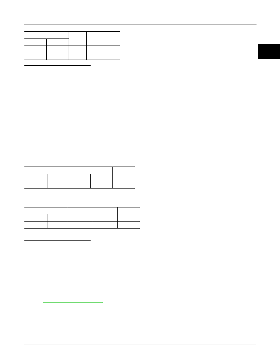
IPDM E/R
Ground
Continuity
Connector
Terminal
E5
12
Ground
Existed
E6
41
IPDM E/R
Cooling fan control module
Continuity
Connector
Terminal
Connector
Terminal
E9
97
E37
2
Existed
Cooling fan control module
Ground
Voltage
Terminal
4
Ground
Battery voltage
6
COOLING FAN
EC-445
< COMPONENT DIAGNOSIS >
[VQ35HR]
C
D
E
F
G
H
I
J
K
L
M
A
EC
N
P
O
Is the inspection result normal?
YES
>> GO TO 9.
NO
>> GO TO 8.
8.
DETECT MALFUNCTIONING PART
Check the following.
• 10A fuse (No. 42)
• IPDM E/R harness connector E7
• 50A fusible link (letter F)
• Harness for open or short between cooling fan relay and fuse
• Harness for open or short between cooling fan relay and battery
>> Repair open circuit or short to ground or short to power in harness or connectors.
9.
CHECK COOLING FAN CONTROL MODULE POWER SUPPLY CIRCUIT-III
1.
Turn ignition switch OFF.
2.
Disconnect IPDM E/R harness connector E6.
3.
Check the continuity between cooling fan relay harness connector and IPDM E/R harness connector.
4.
Check the continuity between cooling fan relay harness connector and cooling fan control module harness
connector.
5.
Also check harness for short to ground and short to power.
Is the inspection result normal?
YES
>> GO TO 10.
NO
>> Repair open circuit or short to ground or short to power in harness or connectors.
10.
CHECK COOLING FAN RELAY
EC-446, "Component Inspection (Cooling Fan Relay)"
Is the inspection result normal?
YES
>> GO TO 11.
NO
>> Replace cooling fan relay.
11.
CHECK INTERMITTENT INCIDENT
Perform
GI-38, "Intermittent Incident"
.
Is the inspection result normal?
YES
>> Replace IPDM E/R.
NO
>> Repair or replace harness connectors.
Component Inspection (Cooling Fan Motor)
INFOID:0000000003133628
1.
CHECK COOLING FAN MOTOR
1.
Turn ignition switch OFF.
Cooling fan relay
Ground
Voltage
Connector
Terminal
E17
1
Ground
Battery voltage
3
Cooling fan relay
IPDM E/R
Continuity
Connector
Terminal
Connector
Terminal
E17
2
E6
42
Existed
Cooling fan relay
Cooling fan control module
Continuity
Connector
Terminal
Connector
Terminal
E17
5
E37
3
Existed
Нет комментариевНе стесняйтесь поделиться с нами вашим ценным мнением.
Текст