Infiniti EX35. Manual — part 1535
WT-96
< PREPARATION >
PREPARATION
PREPARATION
PREPARATION
Special Service Tool
INFOID:0000000003579769
The actual shapes of Kent-Moore tools may differ from those of special service tools illustrated here.
Commercial Service Tool
INFOID:0000000003579770
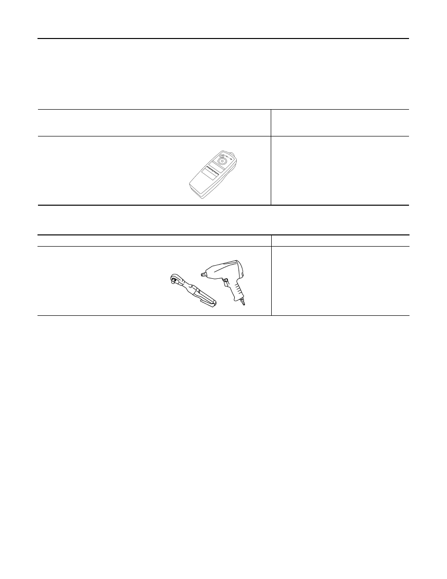
Tool number
(Kent-Moore No.)
Tool name
Description
–
(J-45295)
Transmitter activation tool
ID registration
SEIA0462E
Tool name
Description
Power tool
Loosening wheel nuts
PBIC0190E
ROAD WHEEL
WT-97
< ON-VEHICLE MAINTENANCE >
C
D
F
G
H
I
J
K
L
M
A
B
WT
N
O
P
ON-VEHICLE MAINTENANCE
ROAD WHEEL
Inspection
INFOID:0000000003579771
ALUMINUM WHEEL
1.
Check tires for wear and improper inflation.
2.
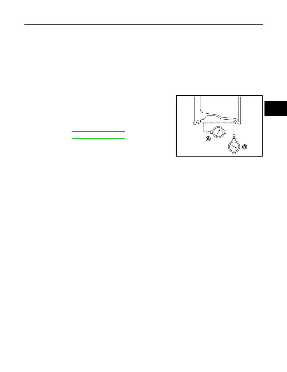
Check wheels for deformation, cracks and other damage. If deformed, remove wheel and check wheel
runout.
a.
Remove tire from aluminum wheel and mount on a tire balance machine.
b.
Set dial indicator as shown in the figure.
c.
If the lateral deflection (A) or vertical deflection (B) for radial
runout value exceeds the limit, replace aluminum wheel.
Limit
A:
Refer to
B:
Refer to
SEIA0737E
WT-98
< ON-VEHICLE REPAIR >
ROAD WHEEL TIRE ASSEMBLY
ON-VEHICLE REPAIR
ROAD WHEEL TIRE ASSEMBLY
Adjustment
INFOID:0000000003579772
BALANCING WHEELS (BONDING WEIGHT TYPE)
Preparation Before Adjustment
Using releasing agent, remove double-faced adhesive tape from the road wheel.
CAUTION:
• Be careful not to scratch the road wheel during removal.
• After removing double-faced adhesive tape, wipe clean traces of releasing agent from the road
wheel.
Wheel Balance Adjustment
If a tire balance machine has adhesion balance weight mode settings and drive-in weight mode setting, select
and adjust a drive-in weight mode suitable for road wheels.
1.
Set road wheel on tire balance machine using the center hole as a guide. Start the tire balance machine.
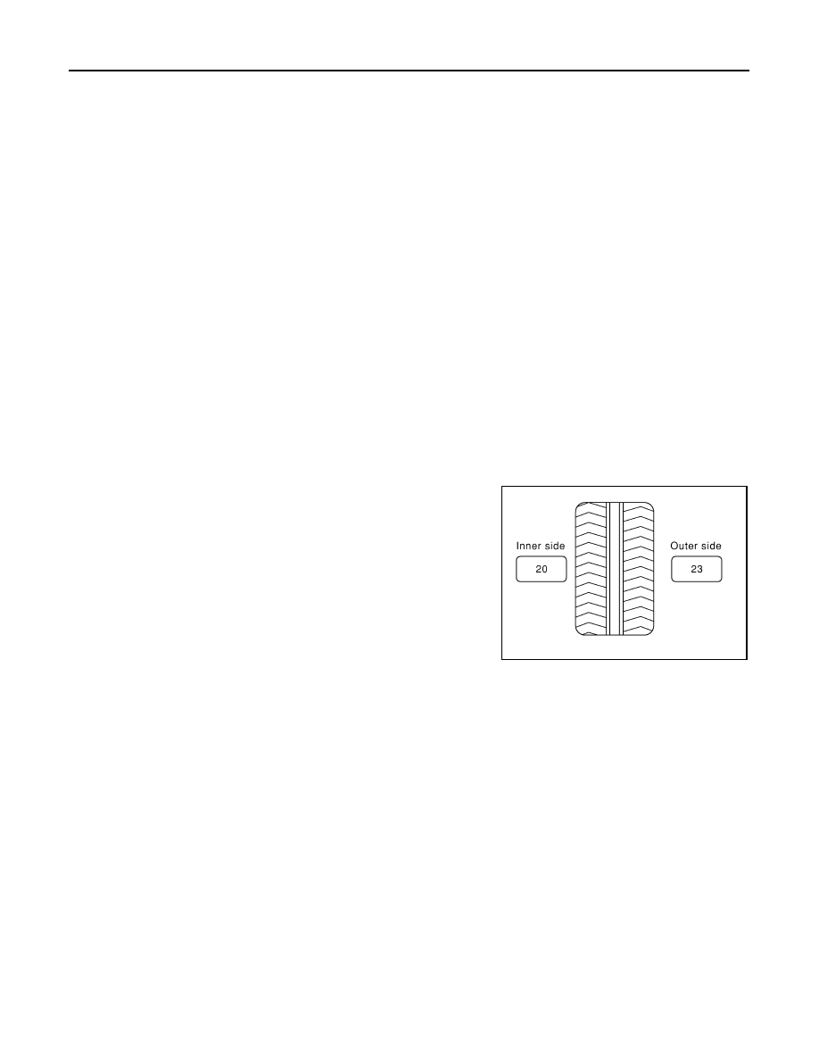
2.
When inner and outer unbalance values are shown on the tire balance machine indicator, multiply outer
unbalance value by 5/3 to determine balance weight that should be used. Select the outer balance weight
with a value closest to the calculated value above and install to the designated outer position of, or at the
designated angle in relation to the road wheel.
CAUTION:
• Do not install the inner balance weight before installing the outer balance weight.
• Before installing the balance weight, be sure to clean the mating surface of the road wheel.
a.
Indicated unbalance value
×
5/3 = balance weight to be installed
Calculation example:
23 g (0.81 oz)
×
5/3 = 38.33 g (1.35 oz)
⇒
37.5 g (1.32 oz) bal-
ance weight (closer to calculated balance weight value)
NOTE:
Note that balance weight value must be closer to the calculated
balance weight value.
Example:
36.2
⇒
35 g (1.23 oz)
36.3
⇒
37.5 g (1.32 oz)
b.
Installed balance weight in the position.
SMA054D
ROAD WHEEL TIRE ASSEMBLY
WT-99
< ON-VEHICLE REPAIR >
C
D
F
G
H
I
J
K
L
M
A
B
WT
N
O
P
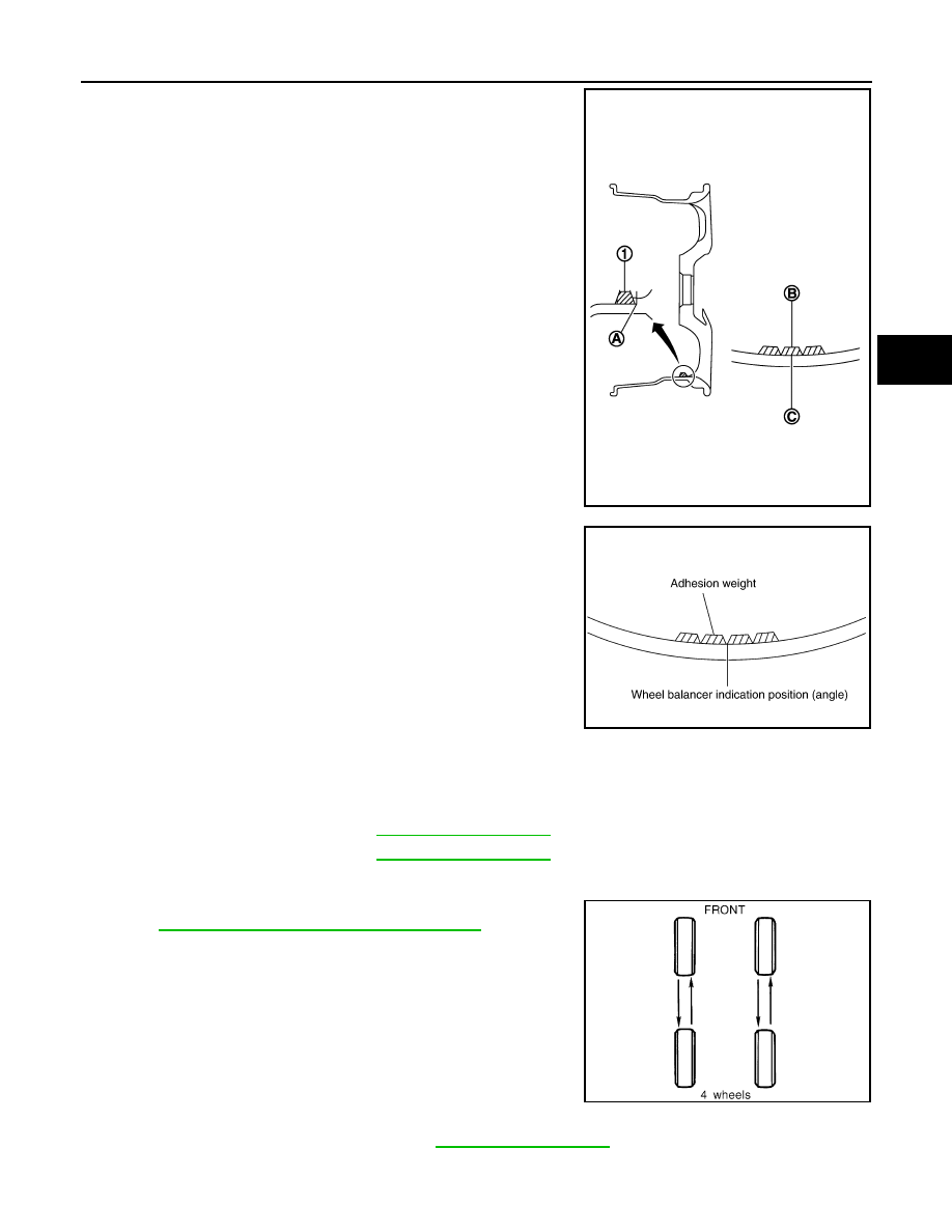
• When installing balance weight (1) to road wheels, set it into
the grooved area (A) on the inner wall of the road wheel as
shown in the figure so that the balance weight center (B) is
aligned with the tire balance machine indication position
(angle) (C).
CAUTION:
• Always use genuine NISSAN adhesion balance weights.
• Balance weights are non-reusable; always replace with
new ones.
• Do not install more than three sheets of balance weight.
c.
If calculated balance weight value exceeds 50 g (1.76 oz), install
two balance weight sheets in line with each other as shown in
the figure.
CAUTION:
Do not install one balance weight sheet on top of another.
3.
Start the tire balance machine again.
4.
Install drive-in balance weight on inner side of road wheel in the
tire balance machine indication position (angle).
CAUTION:
Do not install more than two balance weight.
5.
Start the tire balance machine. Make sure that inner and outer
residual unbalance values are 5 g (0.17 oz) each or below.
6.
If either residual unbalance value exceeds 5 g (0.17 oz), repeat installation procedures.
TIRE ROTATION
• Follow the maintenance schedule for tire rotation service intervals.
MA-4, "Explanation of General Maintenance"
.
• When installing the wheel, tighten wheel nuts to the specified
torque.
CAUTION:
• Do not include the T-type spare tire when rotating the tires.
• When installing wheels, tighten them diagonally by dividing
the work two to three times in order to prevent the wheels
from developing any distortion.
• Be careful not to tighten wheel nut at torque exceeding the
criteria for preventing strain of disc rotor.
• Use NISSAN genuine wheel nuts for aluminum wheels.
JPEIC0040ZZ
Limit
Dynamic (At flange):
Refer to
.
Static (At flange):
Refer to
.
PEIA0033E
Wheel nuts tighting torque
: Refer to
.
SMA829C
Нет комментариевНе стесняйтесь поделиться с нами вашим ценным мнением.
Текст