Infiniti EX35. Manual — part 651
EC-346
< COMPONENT DIAGNOSIS >
[VQ35HR]
P1078, P1084 EVT CONTROL POSITION SENSOR
Is the inspection result normal?
YES
>> GO TO 5.
NO
>> Repair short to ground or short to power in harness or connectors.
5.
CHECK COMPONENTS
Check the following.
• Crankshaft position sensor (POS) (Refer to
EC-255, "Component Inspection"
• Camshaft position sensor (PHASE) (bank 2) (Refer to
EC-260, "Component Inspection"
• Battery current sensor (Refer to
EC-379, "Component Inspection"
.)
• EVAP control system pressure sensor (Refer to
EC-296, "Component Inspection"
.)
• Refrigerant pressure sensor (Refer to
Is the inspection result normal?
YES
>> GO TO 6.
NO
>> Replace malfunctioning component.
6.
CHECK APP SENSOR
EC-423, "Component Inspection"
Is the inspection result normal?
YES
>> GO TO 15.
NO
>> GO TO 7.
7.
REPLACE ACCELERATOR PEDAL ASSEMBLY
1.
Replace accelerator pedal assembly.
2.
Go to
EC-423, "Special Repair Requirement"
.
>> INSPECTION END
8.
CHECK EXHAUST VALVE TIMING CONTROL POSITION SENSOR GROUND CIRCUIT FOR OPEN AND
SHORT
1.
Turn ignition switch OFF.
2.
Disconnect ECM harness connector.
3.
Check the continuity between exhaust valve timing control position sensor harness connector and ECM
harness connector.
4.
Also check harness for short to ground and short to power.
Is the inspection result normal?
YES
>> GO TO 9.
NO
>> Repair open circuit or short to ground or short to power in harness or connectors.
9.
CHECK EXHAUST VALVE TIMING CONTROL POSITION SENSOR INPUT SIGNAL CIRCUIT FOR OPEN
AND SHORT
F102
64
CMP sensor (PHASE) (bank 2)
F18
1
EVT control position sensor (bank 2)
F19
1
Battery current sensor
E21
1
M107
103
APP sensor
E112
6
107
EVAP control system pressure sensor
B252
3
111
Refrigerant pressure sensor
E77
3
ECM
Sensor
Connector
Terminal
Name
Connector
Terminal
DTC
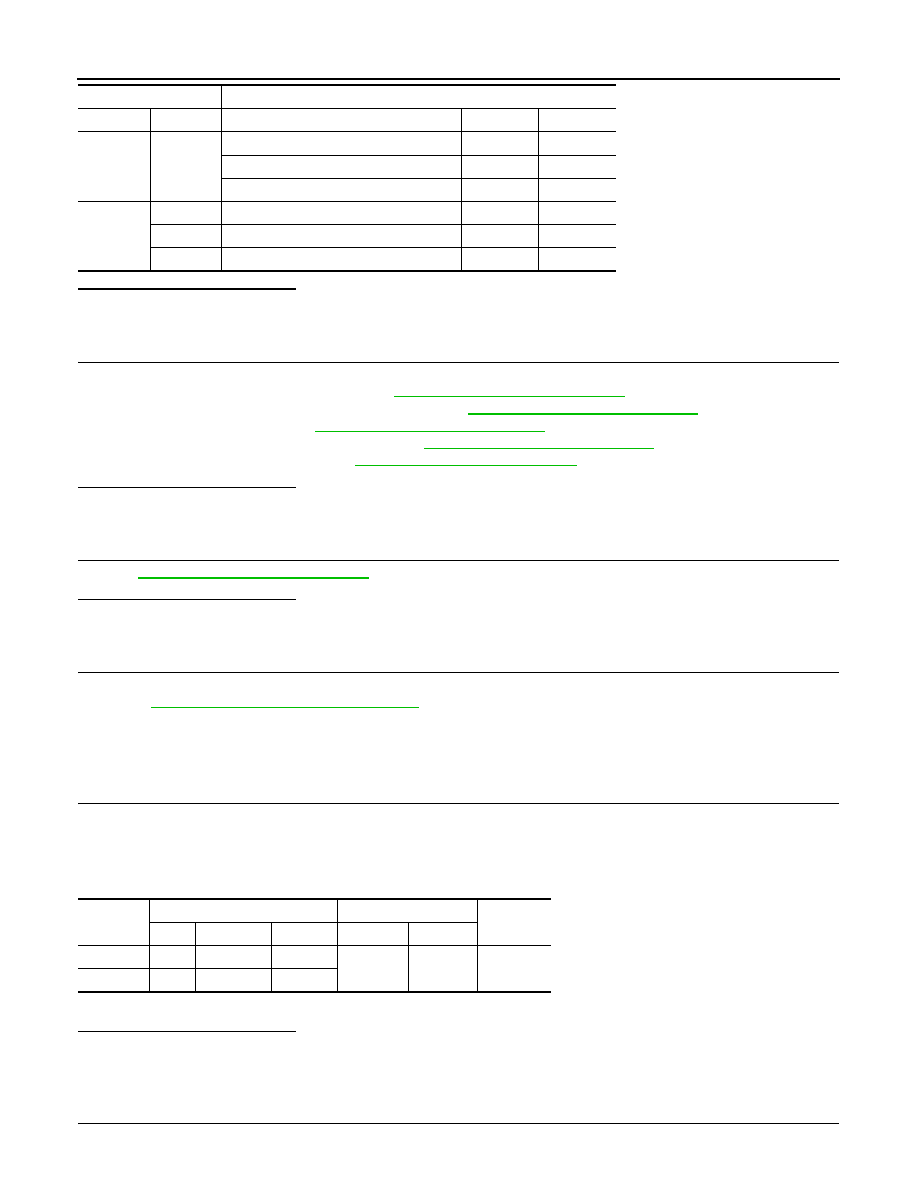
EVT control position sensor
ECM
Continuity
Bank
Connector
Terminal
Connector
Terminal
P1078
1
F4
2
F102
88
Existed
P1084
2
F19
2
P1078, P1084 EVT CONTROL POSITION SENSOR
EC-347
< COMPONENT DIAGNOSIS >
[VQ35HR]
C
D
E
F
G
H
I
J
K
L
M
A
EC
N
P
O
1.
Check the continuity between exhaust valve timing control position sensor harness connector and ECM
harness connector.
2.
Also check harness for short to ground and short to power.
Is the inspection result normal?
YES
>> GO TO 11.
NO
>> GO TO 10.
10.
DETECT MALFUNCTIONING PART
Check the following.
• Harness connectors F107, F106
• Harness for open or short between exhaust valve timing control position sensor and ECM
>> Repair open circuit or short to ground or short to power in harness or connectors.
11.
CHECK EXHAUST VALVE TIMING CONTROL POSITION SENSOR
EC-348, "Component Inspection"
Is the inspection result normal?
YES
>> GO TO 12.
NO
>> Replace malfunctioning exhaust valve timing control position sensor.
12.
CHECK CRANKSHAFT POSITION SENSOR (POS)
EC-255, "Component Inspection"
Is the inspection result normal?
YES
>> GO TO 13.
NO
>> Replace crankshaft position sensor (POS).
13.
CHECK CAMSHAFT POSITION SENSOR (PHASE)
EC-260, "Component Inspection"
Is the inspection result normal?
YES
>> GO TO 14.
NO
>> Replace malfunctioning camshaft position sensor (PHASE).
14.
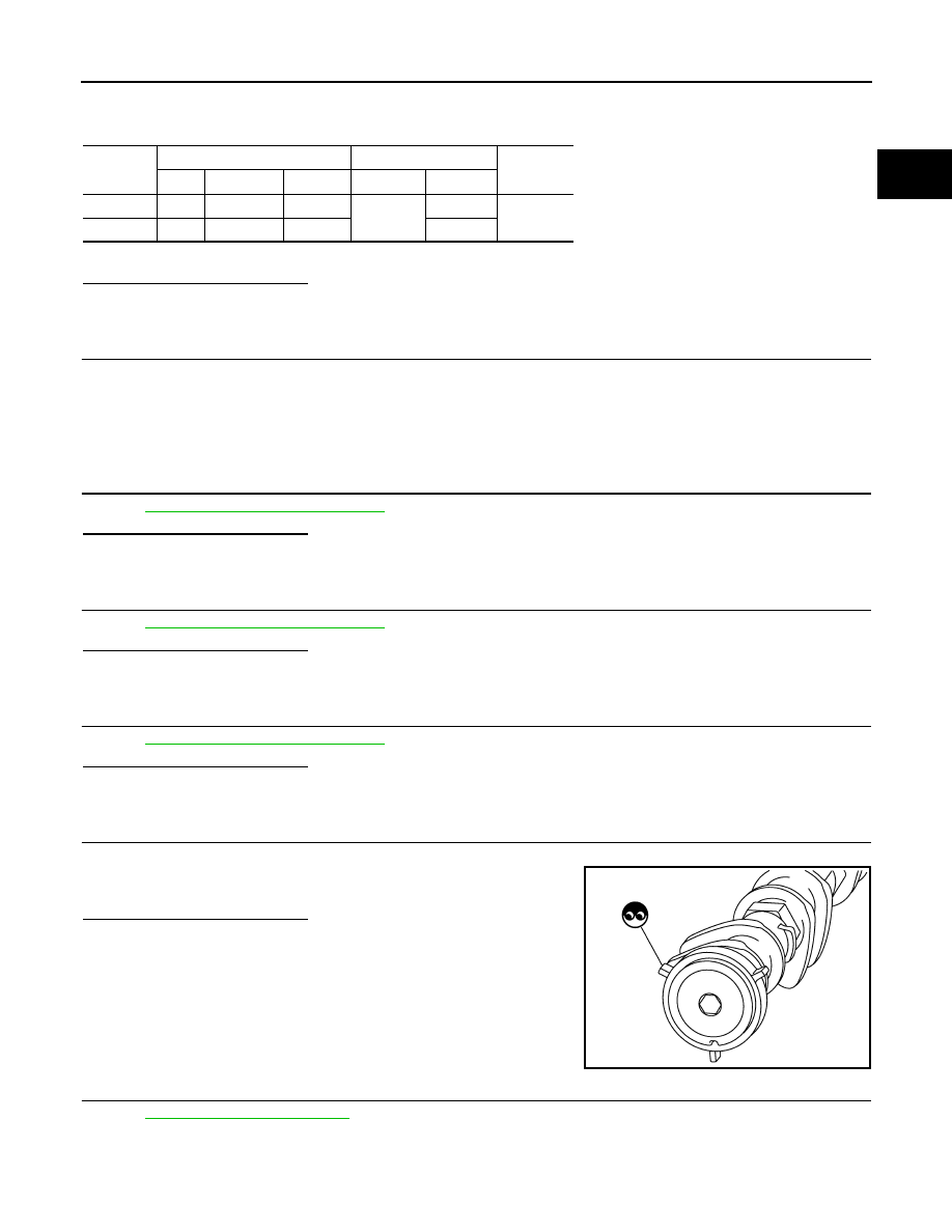
CHECK CAMSHAFT (EXH)
Check the following;
• Accumulation of debris to the signal plate of camshaft rear end
• Chipping signal plate of camshaft rear end
Is the inspection result normal?
YES
>> GO TO 15.
NO
>> Remove debris and clean the signal plate of camshaft
rear end or replace camshaft.
15.
CHECK INTERMITTENT INCIDENT
GI-38, "Intermittent Incident"
.
>> INSPECTION END
DTC
EVT control position sensor
ECM
Continuity
Bank
Connector
Terminal
Connector
Terminal
P1078
1
F4
3
F102
58
Existed
P1084
2
F19
3
62
JMBIA0059ZZ
EC-348
< COMPONENT DIAGNOSIS >
[VQ35HR]
P1078, P1084 EVT CONTROL POSITION SENSOR
Component Inspection
INFOID:0000000003133502
1.
EXHAUST VALVE TIMING CONTROL POSITION SENSOR-I
1.
Turn ignition switch OFF.
2.
Disconnect exhaust valve timing control position sensor harness connector.
3.
Loosen the fixing bolt of the sensor.
4.
Remove the sensor.
5.
Visually check the sensor for chipping.
Is the inspection result normal?
YES
>> GO TO 2.
NO
>> Replace malfunctioning exhaust valve timing control
position sensor.
2.
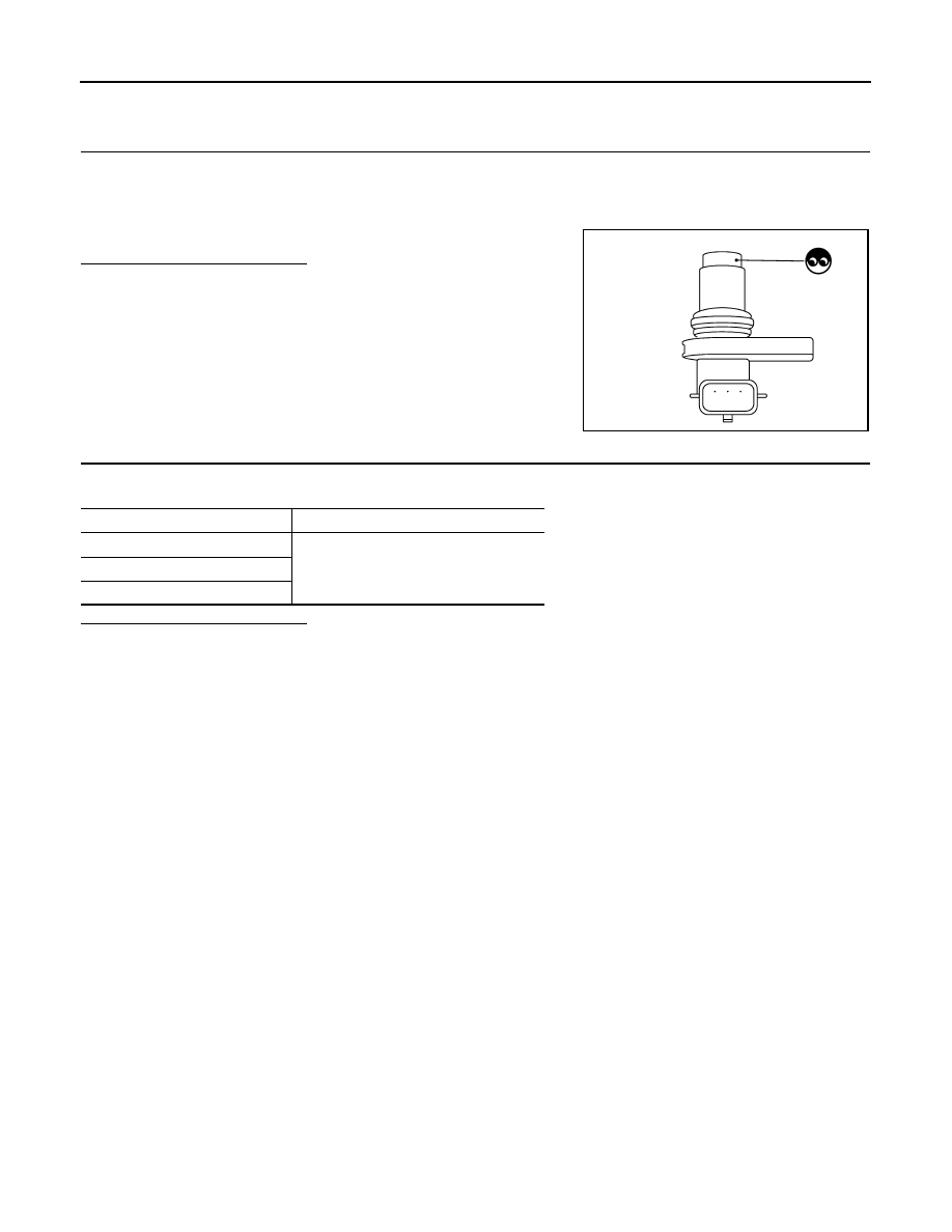
EXHAUST VALVE TIMING CONTROL POSITION SENSOR-II
Check resistance exhaust valve timing control position sensor terminals as shown below.
Is the inspection result normal?
YES
>> INSPECTION END
NO
>> Replace malfunctioning exhaust valve timing control position sensor.
JMBIA0065ZZ
Terminals
Resistance
1 (+) - 2 (-)
Except 0 or
∞
Ω
[at 25
°
C (77
°
F)]
1 (+) - 3 (-)
2 (+) - 3 (-)

P1148, P1168 CLOSED LOOP CONTROL
EC-349
< COMPONENT DIAGNOSIS >
[VQ35HR]
C
D
E
F
G
H
I
J
K
L
M
A
EC
N
P
O
P1148, P1168 CLOSED LOOP CONTROL
DTC Logic
INFOID:0000000003133503
DTC DETECTION LOGIC
NOTE:
DTC P1148 or P1168 is displayed with another DTC for A/F sensor 1.
Perform the trouble diagnosis for the corresponding DTC.
DTC No.
Trouble diagnosis name
DTC detecting condition
Possible cause
P1148
Closed loop control
function (bank 1)
The closed loop control function for bank 1 does
not operate even when vehicle is driving in the
specified condition.
• Harness or connectors
(The A/F sensor 1 circuit is open or short-
ed.)
• A/F sensor 1
• A/F sensor 1 heater
P1168
Closed loop control
function (bank 2)
The closed loop control function for bank 2 does
not operate even when vehicle is driving in the
specified condition.
Нет комментариевНе стесняйтесь поделиться с нами вашим ценным мнением.
Текст