Infiniti EX35. Manual — part 652

EC-350
< COMPONENT DIAGNOSIS >
[VQ35HR]
P1211 TCS CONTROL UNIT
P1211 TCS CONTROL UNIT
Description
INFOID:0000000003133504
The malfunction information related to TCS is transferred through the CAN communication line from “ABS
actuator and electric unit (control unit)” to ECM.
Be sure to erase the malfunction information such as DTC not only for “ABS actuator and electric unit
(control unit)” but also for ECM after TCS related repair.
DTC Logic
INFOID:0000000003133505
DTC DETECTION LOGIC
Freeze frame data is not stored in the ECM for this self-diagnosis.
DTC CONFIRMATION PROCEDURE
1.
PRECONDITIONING
TESTING CONDITION:
Before performing the following procedure, confirm that battery voltage is more than 10.5 V at idle.
>> GO TO 2.
2.
PERFORM DTC CONFIRMATION PROCEDURE
1.
Start engine and let it idle for at least 60 seconds.
2.
Check 1st trip DTC.
Is 1st trip DTC detected?
YES
>>
NO
>> INSPECTION END
Diagnosis Procedure
INFOID:0000000003133506
Go to
DTC No.
Trouble diagnosis name
DTC detecting condition
Possible cause
P1211
TCS control unit
ECM receives a malfunction information from
“ABS actuator and electric unit (control unit)”.
• ABS actuator and electric unit (control
unit)
• TCS related parts

P1212 TCS COMMUNICATION LINE
EC-351
< COMPONENT DIAGNOSIS >
[VQ35HR]
C
D
E
F
G
H
I
J
K
L
M
A
EC
N
P
O
P1212 TCS COMMUNICATION LINE
Description
INFOID:0000000003133507
This CAN communication line is used to control the smooth engine operation during the TCS operation. Pulse
signals are exchanged between ECM and “ABS actuator and electric unit (control unit)”.
Be sure to erase the malfunction information such as DTC not only for “ABS actuator and electric unit
(control unit)” but also for ECM after TCS related repair.
DTC Logic
INFOID:0000000003133508
DTC DETECTION LOGIC
NOTE:
• If DTC P1212 is displayed with DTC U1000 or U1001, first perform the trouble diagnosis for DTC
U1000, U1001. Refer to
• If DTC P1212 is displayed with DTC P0607, first perform the trouble diagnosis for DTC P0607. Refer
.
Freeze frame data is not stored in the ECM for this self-diagnosis.
DTC CONFIRMATION PROCEDURE
1.
PRECONDITIONING
TESTING CONDITION:
Before performing the following procedure, confirm that battery voltage is more than 10.5 V at idle.
>> GO TO 2.
2.
PERFORM DTC CONFIRMATION PROCEDURE
1.
Start engine and let it idle for at least 10 seconds.
2.
Check 1st trip DTC.
Is 1st trip DTC detected?
YES
>> Go to
NO
>> INSPECTION END
Diagnosis Procedure
INFOID:0000000003133509
DTC No.
Trouble diagnosis name
DTC detecting condition
Possible cause
P1212
TCS communication line
ECM can not receive the information from
“ABS actuator and electric unit (control
unit)” continuously.
• Harness or connectors
(The CAN communication line is open or short-
ed.)
• ABS actuator and electric unit (control unit)
• Dead (Weak) battery

EC-352
< COMPONENT DIAGNOSIS >
[VQ35HR]
P1217 ENGINE OVER TEMPERATURE
P1217 ENGINE OVER TEMPERATURE
DTC Logic
INFOID:0000000003133510
DTC DETECTION LOGIC
NOTE:
• If DTC P1217 is displayed with DTC U1000 or U1001, first perform the trouble diagnosis for DTC
U1000, U1001. Refer to
.
• If DTC P1217 is displayed with DTC P0607, first perform the trouble diagnosis for DTC P0607. Refer
If the cooling fan or another component in the cooling system malfunctions, engine coolant temperature will
rise.
When the engine coolant temperature reaches an abnormally high temperature condition, a malfunction is
indicated.
CAUTION:
When a malfunction is indicated, be sure to replace the coolant. Refer to
. Also, replace the engine oil. Refer to
.
1.
Fill radiator with coolant up to specified level with a filling speed of 2 liters per minute. Be sure to
use coolant with the proper mixture ratio. Refer to
MA-11, "Anti-Freeze Coolant Mixture Ratio"
2.
After refilling coolant, run engine to ensure that no water-flow noise is emitted.
DTC CONFIRMATION PROCEDURE
1.
PERFORM COMPONENT FUNCTION CHECK
Perform component function check. Refer to
EC-352, "Component Function Check"
NOTE:
Use component function check to check the overall function of the cooling fan. During this check, a DTC might
not be confirmed.
Is the inspection result normal?
YES
>> INSPECTION END
NO
>> Go to
Component Function Check
INFOID:0000000003133511
1.
PERFORM COMPONENT FUNCTION CHECK-I
WARNING:
Never remove the radiator cap when the engine is hot. Serious burns could be caused by high pres-
sure fluid escaping from the radiator.
Wrap a thick cloth around cap. Carefully remove the cap by turning it a quarter turn to allow built-up
pressure to escape. Then turn the cap all the way off.
DTC No.
Trouble diagnosis name
DTC detecting condition
Possible cause
P1217
Engine over tempera-
ture (Overheat)
• Cooling fan does not operate properly (Over-
heat).
• Cooling fan system does not operate proper-
ly (Overheat).
• Engine coolant was not added to the system
using the proper filling method.
• Engine coolant is not within the specified
range.
• Harness or connectors
(The cooling fan circuit is open or short-
ed.)
• IPDM E/R
• Cooling fan control module
• Cooling fan motor
• Radiator hose
• Radiator
• Radiator cap
• Water pump
• Thermostat
P1217 ENGINE OVER TEMPERATURE
EC-353
< COMPONENT DIAGNOSIS >
[VQ35HR]
C
D
E
F
G
H
I
J
K
L
M
A
EC
N
P
O
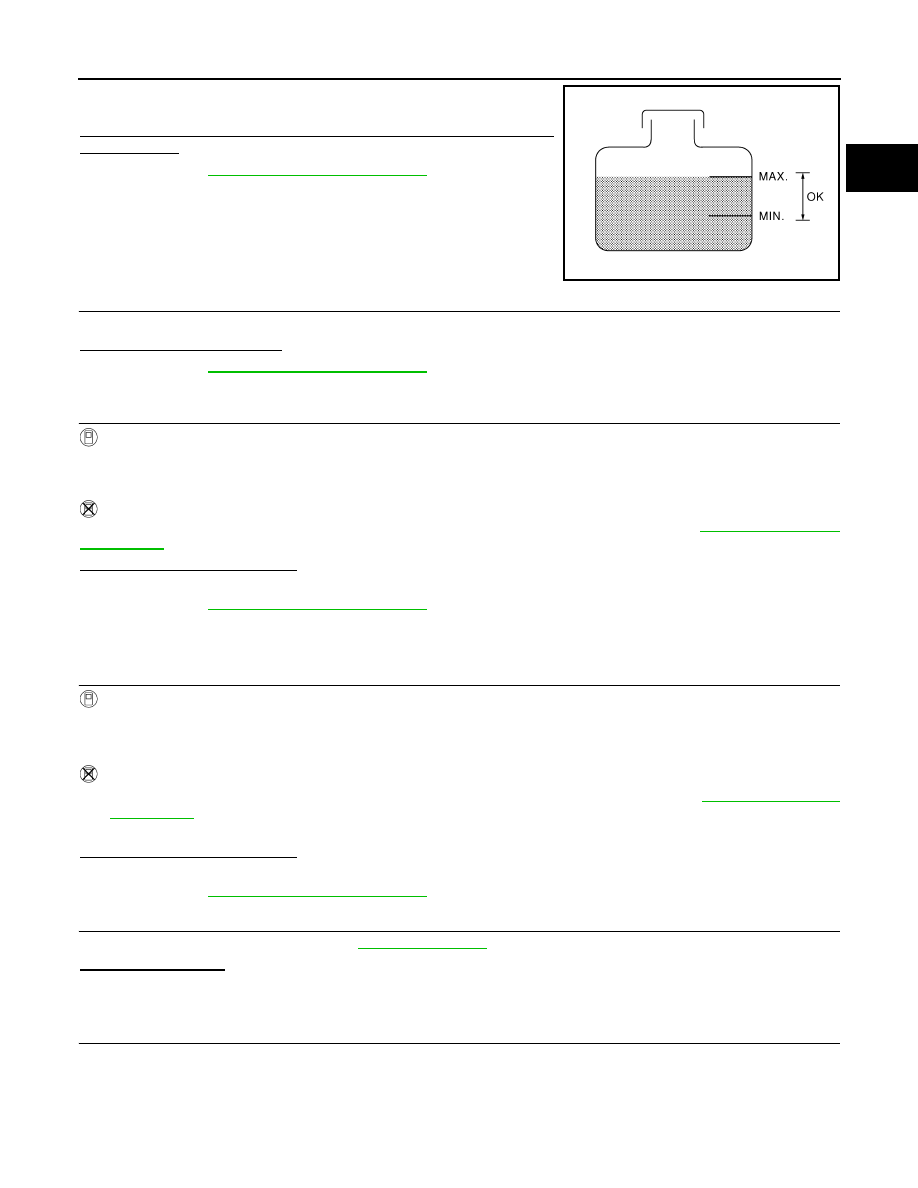
Check the coolant level in the reservoir tank and radiator.
Allow engine to cool before checking coolant level.
Is the coolant level in the reservoir tank and/or radiator below the
proper range?
YES
>> Go to
NO
>> GO TO 2.
2.
PERFORM COMPONENT FUNCTION CHECK-II
Confirm whether customer filled the coolant or not.
Did customer fill the coolant?
YES
>> Go to
NO
>> GO TO 3.
3.
PERFORM COMPONENT FUNCTION CHECK-III
With CONSULT-III
1.
Turn ignition switch ON.
2.
Perform “FAN DUTY CONTROL” in “ACTIVE TEST” mode with CONSULT-III.
3.
Check that cooling fan speed varies according to the percent.
Without CONSULT-III
Perform IPDM E/R auto active test and check cooling fan motors operation, refer to
.
Is the inspection result normal?
YES
>> INSPECTION END
NO
>> Go to
Diagnosis Procedure
INFOID:0000000003133512
1.
CHECK COOLING FAN OPERATION
With CONSULT-III
1.
Turn ignition switch ON.
2.
Perform “FAN DUTY CONTROL” in “ACTIVE TEST” mode with CONSULT-III.
3.
Check that cooling fan speed varies according to the percent.
Without CONSULT-III
1.
Perform IPDM E/R auto active test and check cooling fan motors operation, refer to
.
2.
Check that cooling fan operates.
Is the inspection result normal?
YES
>> GO TO 2.
NO
>> Go to
2.
CHECK COOLING SYSTEM FOR LEAK-I
Check cooling system for leak. Refer to
Is leakage detected?
YES
>> GO TO 3.
NO
>> GO TO 4.
3.
CHECK COOLING SYSTEM FOR LEAK-II
Check the following for leak.
• Hose
• Radiator
• Water pump
SEF621W
Нет комментариевНе стесняйтесь поделиться с нами вашим ценным мнением.
Текст