Infiniti EX35. Manual — part 167
AV
MULTI AV SYSTEM
AV-449
< FUNCTION DIAGNOSIS >
[BOSE AUDIO WITH NAVIGATION]
C
D
E
F
G
H
I
J
K
L
M
B
A
O
P
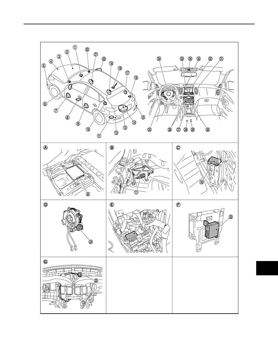
Component Parts Location
INFOID:0000000003160601
1.
Center speaker
2.
Corner sensor front RH
3.
Front squawker LH
4.
Front camera
5.
Corner sensor front LH
6.
Side camera LH
JPNIA0911ZZ

AV-450
< FUNCTION DIAGNOSIS >
[BOSE AUDIO WITH NAVIGATION]
MULTI AV SYSTEM
Component Description
INFOID:0000000003515919
7.
Front door speaker LH
8.
• Around view monitor control unit
(with around view monitor)
• Camera control unit (with rear view
monitor)
9.
Rear door speaker LH
10. Rear squawker LH
11. BOSE amp.
12. Corner sensor rear LH
13. Woofer
14. • Rear camera (with around view
monitor)
• Rear view camera (with rear view
monitor)
15. Corner sensor rear RH
16. Buzzer
17. Rear squawker RH
18. Antenna base (antenna amp and sat-
ellite antenna)
19. Rear door speaker RH
20. Side camera RH
21. Front door speaker RH
22. Front squawker RH
23. Display unit
24. Steering angle sensor
25. Steering switch
26. Preset switch
27. Sonar control unit (with around view
monitor)
28. iPod connector
29. Auxiliary input jacks
30. AV control unit
31. Multifunction switch
32. iPod adapter
33. GPS antenna
34. Microphone
A.
Under front seat (LH side)
B.
Luggage floor (LH side)
C.
Luggage side RH
D.
Spiral cable part
E.
Cluster lid C removed condition
F.
Rear view of the display unit
G.
Instrument panel rear side
Part name
Description
AV CONTROL UNIT
• Integrates hard disk drive (HDD) allowing map data and music data to be
stored.
• It is the master unit of the MULTI AV system, and is connected to each control
unit by communication. It operates each system according to communication
signals from AV control unit.
• AV control unit includes the audio, hands-free phone, voice control, navigation,
satellite radio, and vehicle information functions.
• It is connected to ECM, unified meter and A/C amp. via CAN communication
to obtain necessary information for the vehicle information function.
• It is connected to BCM via CAN communication transmitting/receiving for the
vehicle settings function.
• It inputs the illumination signals that are required for the display dimming con-
trol.
• It inputs the signals for driving status recognition (vehicle speed, reverse and
parking brake).
• Update of map data is performed with the CONSULT-III and the applicable ca-
ble.
• AV control unit recognizes the presence of camera system with camera con-
nection recognition signal.
DISPLAY UNIT
• Display image is controlled by the serial communication from AV control unit.
• RGB image signal is input from AV control unit (RGB, RGB area and RGB syn-
chronizing). Auxiliary image signal is input from the auxiliary input jack. Cam-
era image signal is input from camera control unit.
• Synchronize signal (HP, VP) is output to AV control unit.
• Touch panel function can be operated for each system by touching a display
directly.
BOSE AMP.
• Inputs power (amp. ON) and sound signal from AV control unit, and outputs
sound signal to woofer and each speaker.
• Input “Driver's Audio Stage” mode change signal from AV control unit.
• Woofer amp. ON signal is transmitted to woofer.
FRONT DOOR SPEAKER
• Outputs sound signal from BOSE amp.
• Outputs sound (mid and low range).
REAR DOOR SPEAKER
• Outputs sound signal from BOSE amp.
• Outputs sound (mid and low range).

AV
MULTI AV SYSTEM
AV-451
< FUNCTION DIAGNOSIS >
[BOSE AUDIO WITH NAVIGATION]
C
D
E
F
G
H
I
J
K
L
M
B
A
O
P
FRONT SQUAWKER
• Outputs sound signal from BOSE amp.
• Outputs sound (high and mid range).
REAR SQUAWKER
• Outputs sound signal from BOSE amp.
• Outputs sound (high and mid range).
CENTER SPEAKER
• Outputs sound signal from BOSE amp.
• Outputs sound (high and mid range).
WOOFER
• Inputs power (amp. ON) and sound signal from BOSE amp.
• Outputs low-frequency sound.
MULTIFUNCTION SWITCH
• Operation panel is equipped with the centralized switch where audio, auxiliary
input and navigation operations are integrated.
• Connected with preset switch via cable, and operation signal is transmitted to
AV control unit via AV communication.
PRESET SWITCH
• Operation panel is equipped with the centralized switch where audio and air
conditioner operations are integrated.
• Connected with multifunction switch via cable, and operation signal is transmit-
ted to AV control unit via AV communication.
• The disk ejection operating signal is performed by hardwire.
CAMERA CONTROL UNIT
• Camera image signal is input from rear view camera. Camera image signal
output to display unit.
• Power (camera ON signal) is transmitted to rear view camera.
• Superimposes the guiding line, predicted course line and sonar indicator to
camera image that outputs to display unit.
• Input the sensor signal from the steering angle sensor, and then control the
predicted course line.
• Camera control unit is connected via AV communication.
REAR VIEW CAMERA
• The image from rear camera is transmitted to camera control unit.
• It receives power (camera ON signal) from camera control unit and operates.
AROUND VIEW MONITOR CONTROL UNIT
• It supplies power to front camera, rear camera, and side camera. And then it
superimposes the images from each camera and outputs them to display unit.
• Superimpose the guiding line, predicted course line and sonar indicator to the
camera image that outputs to display unit.
• It performs the reception/transmission of communication signal with each cam-
era.
• Inputs the sensor signal from steering angle sensor, and then controls the pre-
dicted course line.
• It transmits the sonar operation signal from sonar control unit and receives the
sonar information from sonar control unit via AV communication.
• It transmits the information received/transmitted with sonar control unit via AV
communication to AV control unit.
FRONT CAMERA
• It inputs the power supply from around view monitor control unit and outputs
the image of the vehicle front to around view monitor control unit.
• It performs the reception/transmission of the communication signal with
around view monitor control unit.
REAR CAMERA
• It inputs the power supply from around view monitor control unit and outputs
the image of the vehicle rear to around view monitor control unit.
• It performs the reception/transmission of the communication signal with
around view monitor control unit.
SIDE CAMERA LH
• It inputs the power supply from around view monitor control unit and outputs
the image of the vehicle LH to around view monitor control unit.
• It performs the reception/transmission of the communication signal with
around view monitor control unit.
SIDE CAMERA RH
• It inputs the power supply from around view monitor control unit and outputs
the image of the vehicle RH to around view monitor control unit.
• It performs the reception/transmission of the communication signal with
around view monitor control unit.
INFRARED LED (AUXILIARY LIGHTING)
• It illuminates around the front RH wheel by the power supply from around view
monitor control unit to improve nighttime visibility of Front-Side view.
• The infrared LED is an invisible light ray.
Part name
Description

AV-452
< FUNCTION DIAGNOSIS >
[BOSE AUDIO WITH NAVIGATION]
MULTI AV SYSTEM
STEERING SWITCH
• Operations for audio, hands-free phone, audio response and navigation, etc.
are possible.
• Steering switch signal (operation signal) is output to AV control unit.
STEERING ANGLE SENSOR
Steering signal necessary for predicted course line control is transmitted to cam-
era control unit or around view monitor control unit.
MICROPHONE
• Used for hands-free phone operation and voice recognition.
• Mic signal is transmitted to AV control unit.
• Power (Mic VCC) is supplied from AV control unit.
AUXILIARY INPUT JACKS
Image signal of auxiliary input is output to display, and sound signal is output to
AV control unit.
GPS ANTENNA
GPS signal is received and transmitted to AV control unit.
ANTENNA BASE
A radio antenna base integrated with radio antenna amp. and satellite radio an-
tenna is adopted.
ANTENNA AMP.
• Radio signal received by rod antenna is amplified and transmitted to AV control
unit.
• Power (antenna amp. ON signal) is supplied from AV control unit.
SATELLITE RADIO ANTENNA
• Receives satellite radio waves and outputs it to satellite radio tuner.
iPod ADAPTER
• Inputs iPod sound signal from iPod
®
, and outputs iPod sound signal to AV con-
trol unit.
• Receiving/transmitting of iPod
®
operation signals are performed as follows:
- between AV control unit and iPod adapter: AV communication.
- between iPod
®
and iPod adapter: serial communication.
SONAR CONTROL UNIT (WITH AROUND VIEW
MONITOR)
• It is connected with around view monitor control unit via AV communication and
receives the sonar operation signal from around view monitor control unit.
• It transmits the sonar detection status to around view monitor control unit via
AV communication.
• It judges the warning level according to the signal from corner sensor and out-
puts the buzzer drive signal.
• Trouble diagnosis is supported with CONSULT-III (K-LINE).
CORNER SENSOR
The obstacle distance is detected. The signal is transmitted to sonar control unit.
BUZZER
The warning buzzer outputs with the signal from sonar control unit.
Part name
Description
Нет комментариевНе стесняйтесь поделиться с нами вашим ценным мнением.
Текст