Infiniti EX35. Manual — part 319
BR-38
< ON-VEHICLE REPAIR >
FRONT DISC BRAKE
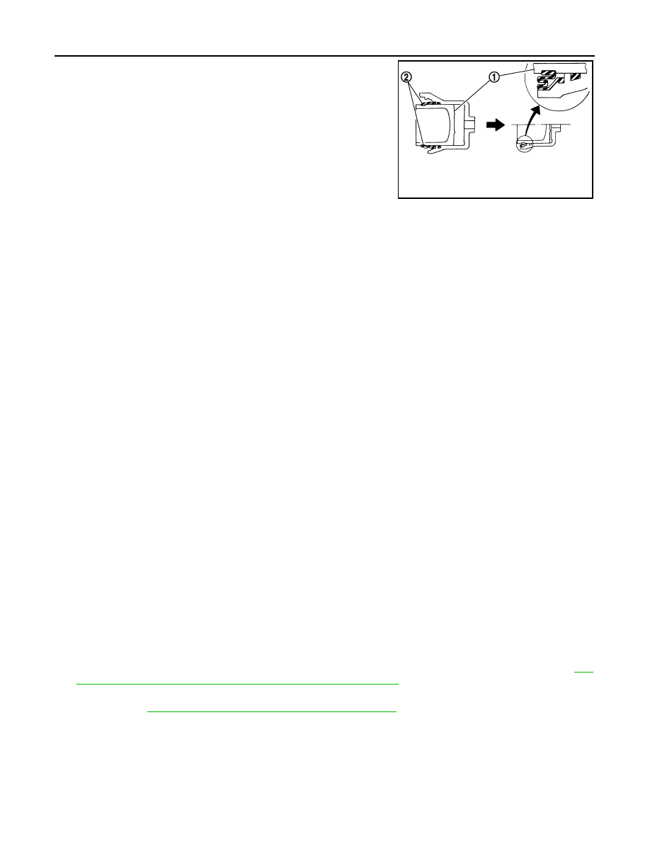
4.
Apply brake fluid to pistons (1). Push piston into cylinder body
by hand and push piston boot (2) piston-side lip into the piston
groove.
CAUTION:
Press the pistons evenly and vary the pressing point to pre-
vent cylinder inner wall from being rubbed.
5.
Apply rubber grease to bushing, and install bushing to sliding
pin.
6.
Apply rubber grease to sliding pins and sliding boots, and install
sliding pins and sliding pin boots to torque member.
7.
Install the cylinder body to the torque member and tighten the
sliding pin bolts to the specified torque.
BRAKE CALIPER ASSEMBLY : Inspection
INFOID:0000000003140020
INSPECTION AFTER DISASSEMBLY
Cylinder Body
Check the inner wall of the cylinder for rust, wear, cracks or damage. Replace the cylinder if any abnormal
condition is detected.
CAUTION:
Always clean with new brake fluid. Never clean with mineral oil such as gasoline and light oil.
Torque Member
Check the torque member for rust, wear, cracks or damage. Replace the member if any abnormal condition is
detected.
Pistons
Check the surface of the piston for rust, wear, cracks or damage. Replace the piston if any abnormal condition
is detected.
CAUTION:
A piston sliding surface is plated. Never polish with sandpaper.
Sliding Pin and Sliding Pin Boot
Check the sliding pins and sliding boots for rust, wear, cracks or damage. Replace the parts if any abnormal
condition is detected.
INSPECTION AFTER INSTALLATION
1.
Check a drag of front disc brake. If any drag is found, follow the procedure described below.
2.
Remove brake pads.
3.
Press the pistons.
CAUTION:
• Never damage the piston boot.
• When replacing a pad with new one, check a brake fluid level in the reservoir tank because brake
fluid returns to master cylinder reservoir tank when pressing piston in.
NOTE:
Use a disc brake piston tool to easily press piston.
4.
Install brake pads.
5.
Depress the brake pedal several times.
6.
Check a drag of front disc brake again. If any drag is found, disassemble the cylinder body. Refer to
36, "BRAKE CALIPER ASSEMBLY : Disassembly and Assembly"
.
7.
Burnish contact surface between disc rotors and brake pads according after refinishing or replacing disc
rotor. Refer to
BR-14, "BRAKE PAD : Inspection and Adjustment"
JPFIA0034ZZ
REAR DISC BRAKE
BR-39
< ON-VEHICLE REPAIR >
C
D
E
G
H
I
J
K
L
M
A
B
BR
N
O
P
REAR DISC BRAKE
BRAKE PAD
BRAKE PAD : Exploded View
INFOID:0000000003140024
BRAKE PAD : Removal and Installation
INFOID:0000000003140025
REMOVAL
WARNING:
Clean any dust from the brake caliper and brake pads with a vacuum dust collector. Never blow with
compressed air.
CAUTION:
• Never depress the brake pedal while removing the brake pads or the cylinder body because the pis-
ton may pop out.
• Never spill or splash brake fluid on the disc rotor.
1.
Remove tires with power tool.
2.
Remove the upper sliding pin bolt.
3.
Suspend the cylinder body with a wire so that the brake hose will not stretch. Remove the brake pads,
shims, shim cover and pad retainers from the torque member.
CAUTION:
• Never deform the pad retainers if removing the pad retainers.
• Never damage the piston boot.
• Never drop the brake pad, shims, and the shim cover.
INSTALLATION
WARNING:
Clean any dust from the brake caliper and brake pads with a vacuum dust collector. Never blow with
compressed air.
CAUTION:
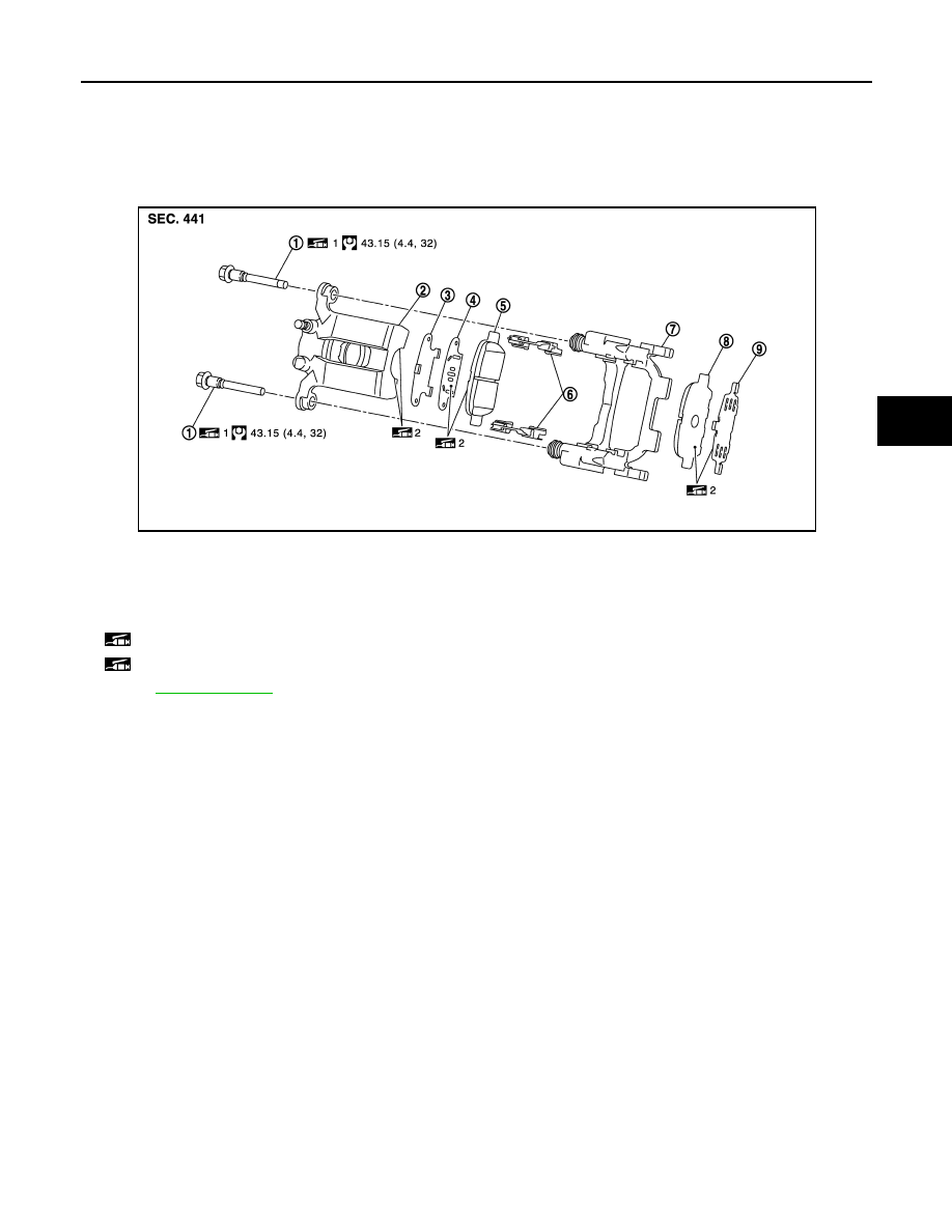
1.
Sliding pin bolt
2.
Cylinder body
3.
Inner shim cover
4.
Inner shim
5.
Inner pad (only right side with pad
wear sensor)
6.
Pad retainer
7.
Torque member
8.
Outer pad
9.
Outer shim
1: Apply rubber grease.
2: Apply PBC (Poly Butyl Cuprysil) grease or silicone-based grease.
Refer to
for symbols not described on the above.
JPFIA0330GB
BR-40
< ON-VEHICLE REPAIR >
REAR DISC BRAKE
• Never depress the brake pedal while removing the brake pads or the cylinder body because the pis-
ton may pop out.
• Never spill or splash brake fluid on the disc rotor.
1.
Apply PBC (Poly Butyl Cuprysil) grease or silicone-based grease to the pad retainers before installing it to
the torque member if the pad retainers has been removed.
CAUTION:
• Securely assemble the pad retainers so that it will not be lifted up from the torque member.
• Never deform the pad retainers.
2.
Apply PBC (Poly Butyl Cuprysil) grease or silicone-based grease to the mating faces between the shims
and the shim cover and install them to the brake pad.
CAUTION:
Always replace the shims together with the shim cover when replacing the brake pad.
3.
Install cylinder body and brake pads to torque member.
CAUTION:
• Never damage the piston boot.
• When of replacing brake pad with new one, check a brake fluid level in the reservoir tank
because brake fluid returns to master cylinder reservoir tank when pressing piston in.
NOTE:
Use a disc brake piston tool to easily press piston.
4.
Install the upper sliding pin bolt and tighten it to the specified torque.
5.
Depress the brake pedal several times to check that no drag feel is present for the rear disc brake. Refer
to
BR-40, "BRAKE PAD : Inspection"
.
BRAKE PAD : Inspection
INFOID:0000000003140026
INSPECTION AFTER REMOVAL
Replace the shims and the shim cover if rust is excessively attached.
INSPECTION AFTER INSTALLATION
1.
Check a drag of front disc brake. If any drag is found, follow the procedure described below.
2.
Remove brake pads.
3.
Press the pistons.
CAUTION:
• Never damage the piston boot.
• When replacing a pad with new one, check a brake fluid level in the reservoir tank because brake
fluid returns to master cylinder reservoir tank when pressing piston in.
NOTE:
Use a disc brake piston tool to easily press piston.
4.
Install brake pads.
5.
Depress the brake pedal several times.
6.
Check a drag of front disc brake again. If any drag is found, disassemble the cylinder body. Refer to
42, "BRAKE CALIPER ASSEMBLY : Disassembly and Assembly"
.
7.
Burnish contact surface between brake pads according after refinishing or replacing brake pads. Refer to
BR-16, "BRAKE PAD : Inspection and Adjustment"
.
BRAKE CALIPER ASSEMBLY
BRAKE CALIPER ASSEMBLY : Exploded View
INFOID:0000000003140031
REMOVAL
REAR DISC BRAKE
BR-41
< ON-VEHICLE REPAIR >
C
D
E
G
H
I
J
K
L
M
A
B
BR
N
O
P
DISASSEMBLY
BRAKE CALIPER ASSEMBLY : Removal and Installation
INFOID:0000000003140032
REMOVAL
WARNING:
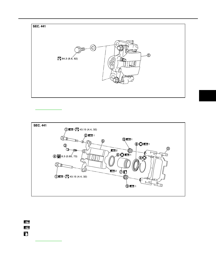
1.
Brake caliper assembly
Refer to
for symbols not described on the above.
JPFIA0311GB
1.
Sliding pin bolt
2.
Bushing
3.
Cap
4.
Bleeder valve
5.
Cylinder body
6.
Piston seal
7.
Piston
8.
Piston boot
9.
Retaining ring
10.
Sliding pin boot
11. Torque member
1: Apply rubber grease.
2: Apply PBC (Poly Butyl Cuprysil) grease or silicone-based grease.
: Apply brake fluid.
Refer to
for symbols not described on the above.
JPFIA0331GB
Нет комментариевНе стесняйтесь поделиться с нами вашим ценным мнением.
Текст