Infiniti EX35. Manual — part 626
EC-246
< COMPONENT DIAGNOSIS >
[VQ35HR]
P0300, P0301, P0302, P0303, P0304, P0305, P0306 MISFIRE
Is the inspection result normal?
YES
>> GO TO 7.
NO
>> Check ignition coil, power transistor and their circuits. Refer to
.
7.
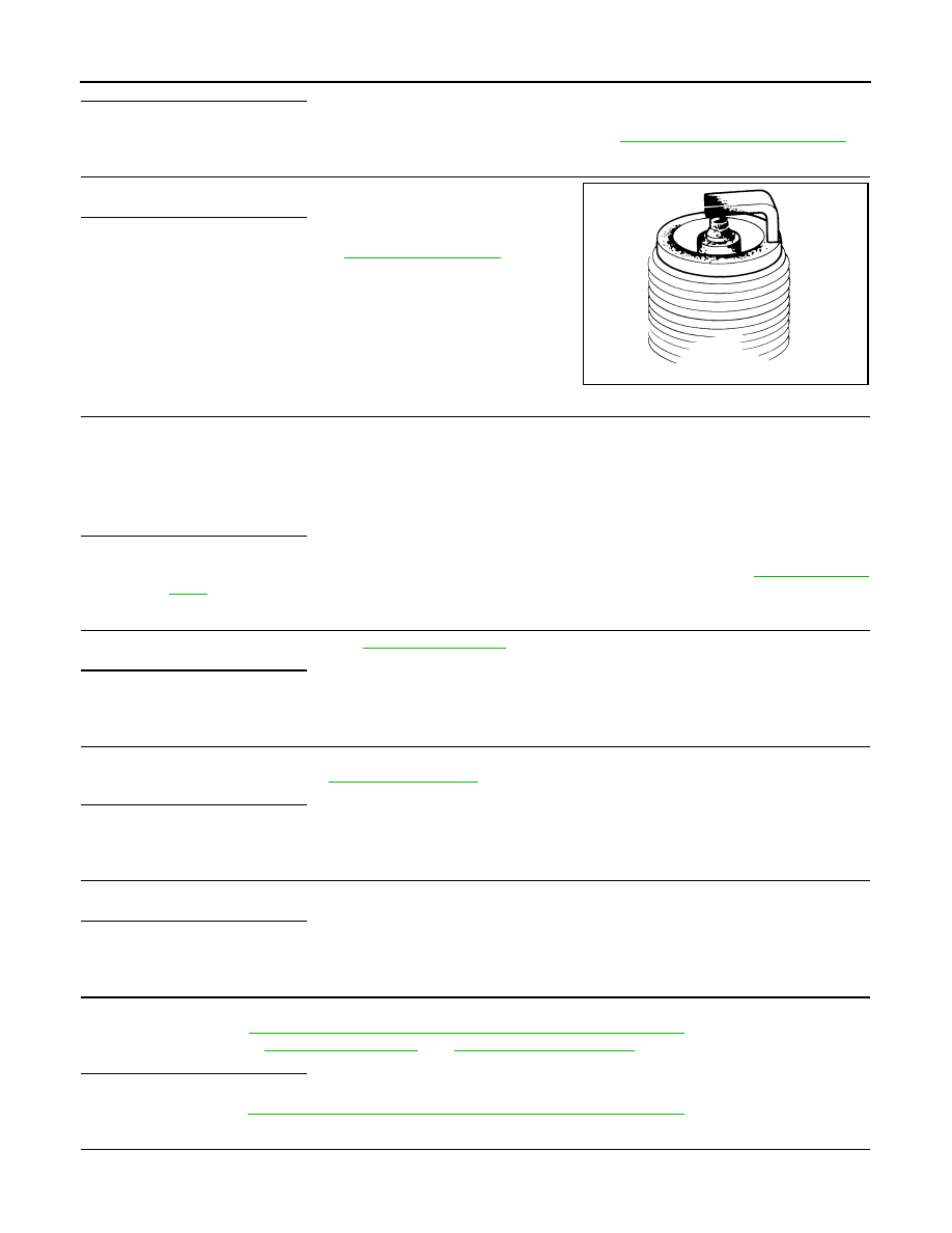
CHECK SPARK PLUG
Check the initial spark plug for fouling, etc.
Is the inspection result normal?
YES
>> Replace spark plug(s) with standard type one(s). For
spark plug type, refer to
.
NO
>> Repair or clean spark plug. Then GO TO 8.
8.
CHECK FUNCTION OF IGNITION COIL-III
1.
Reconnect the initial spark plugs.
2.
Crank engine for about 3 seconds, and recheck whether spark is generated between the spark plug and
the grounded portion.
Is the inspection result normal?
YES
>> INSPECTION END
NO
>> Replace spark plug(s) with standard type one(s). For spark plug type, refer to
.
9.
CHECK COMPRESSION PRESSURE
Check compression pressure. Refer to
.
Is the inspection result normal?
YES
>> GO TO 10.
NO
>> Check pistons, piston rings, valves, valve seats and cylinder head gaskets.
10.
CHECK FUEL PRESSURE
1.
Install all removed parts.
2.
Check fuel pressure. Refer to
.
Is the inspection result normal?
YES
>> GO TO 12.
NO
>> GO TO 11.
11.
DETECT MALFUNCTIONING PART
Check fuel hoses and fuel tubes for clogging.
Is the inspection result normal?
YES
>> Replace “fuel filter and fuel pump assembly”.
NO
>> Repair or replace malfunctioning part.
12.
CHECK IDLE SPEED AND IGNITION TIMING
Check idle speed and ignition timing.
For procedure, refer to
EC-12, "BASIC INSPECTION : Special Repair Requirement"
For specification, refer to
.
Is the inspection result normal?
YES
>> GO TO 13.
NO
>> Follow the
EC-12, "BASIC INSPECTION : Special Repair Requirement"
13.
CHECK A/F SENSOR 1 INPUT SIGNAL CIRCUIT
1.
Turn ignition switch OFF.
2.
Disconnect corresponding A/F sensor 1 harness connector.
SEF156I
Spark should be generated.
P0300, P0301, P0302, P0303, P0304, P0305, P0306 MISFIRE
EC-247
< COMPONENT DIAGNOSIS >
[VQ35HR]
C
D
E
F
G
H
I
J
K
L
M
A
EC
N
P
O
3.
Disconnect ECM harness connector.
4.
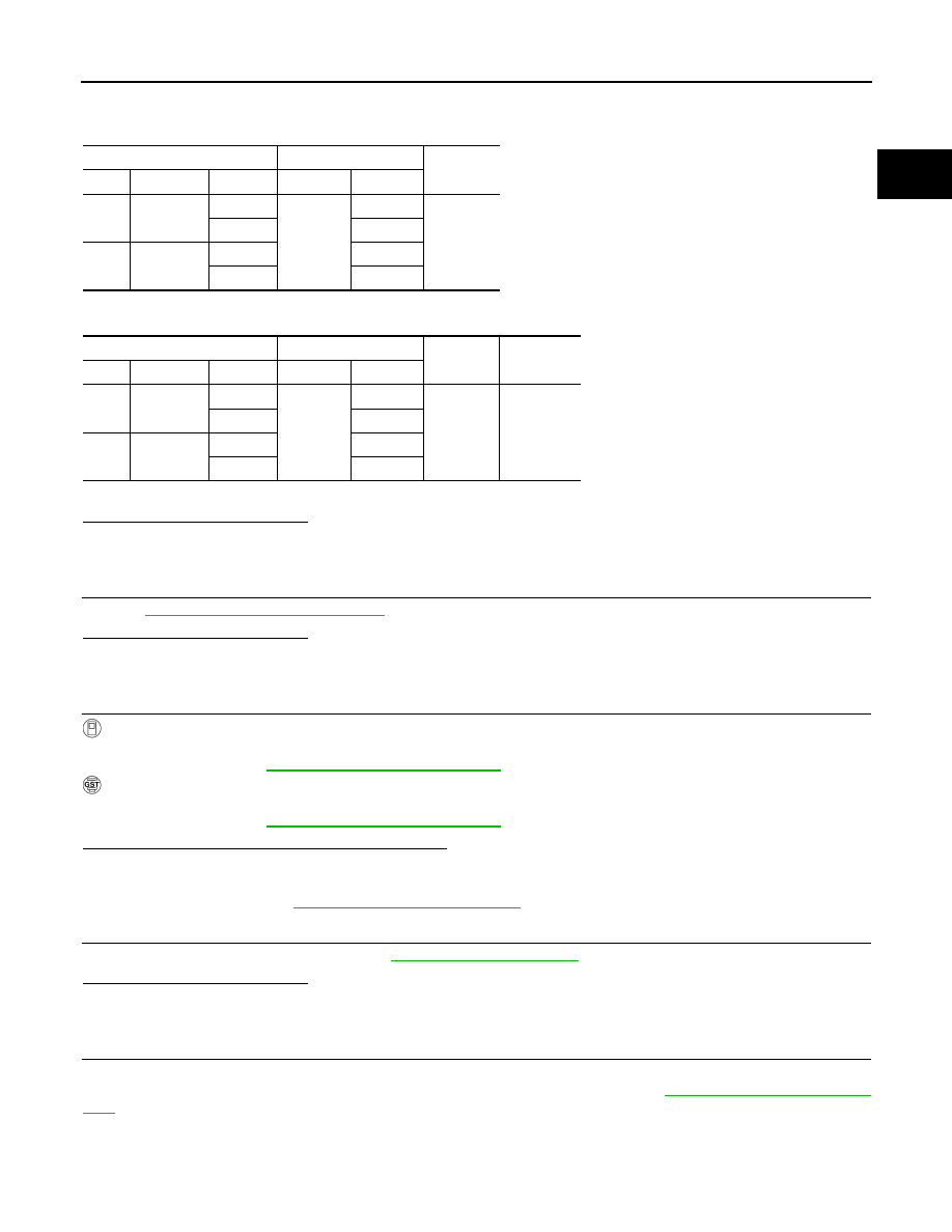
Check the continuity between A/F sensor 1 harness connector and ECM harness connector.
5.
Check the continuity between A/F sensor 1 harness connector or ECM harness connector and ground.
6.
Also check harness for short to power.
Is the inspection result normal?
YES
>> GO TO 14.
NO
>> Repair open circuit or short to ground or short to power in harness or connectors.
14.
CHECK A/F SENSOR 1 HEATER
EC-147, "Component Inspection"
Is the inspection result normal?
YES
>> GO TO 15.
NO
>> Replace (malfunctioning) A/F sensor 1.
15.
CHECK MASS AIR FLOW SENSOR
With CONSULT-III
Check mass air flow sensor signal in “DATA MONITOR” mode with CONSULT-III.
For specification, refer to
EC-543, "Mass Air Flow Sensor"
.
With GST
Check mass air flow sensor signal in Service $01 with GST.
For specification, refer to
EC-543, "Mass Air Flow Sensor"
.
Is the measurement value within the specification?
YES
>> GO TO 16.
NO
>> Check connectors for rusted terminals or loose connections in the mass air flow sensor circuit or
ground. Refer to
16.
CHECK SYMPTOM MATRIX CHART
Check items on the rough idle symptom in
.
Is the inspection result normal?
YES
>> GO TO 17.
NO
>> Repair or replace malfunctioning part.
17.
ERASE THE 1ST TRIP DTC
Some tests may cause a 1st trip DTC to be set.
Erase the 1st trip DTC from the ECM memory after performing the tests. Refer to
.
>> GO TO 18.
A/F sensor 1
ECM
Continuity
Bank
Connector
Terminal
Connector
Terminal
1
F3
1
F102
57
Existed
2
61
2
F20
1
65
2
66
A/F sensor 1
ECM
Ground
Continuity
Bank
Connector
Terminal
Connector
Terminal
1
F3
1
F102
57
Ground
Not existed
2
61
2
F20
1
65
2
66
EC-248
< COMPONENT DIAGNOSIS >
[VQ35HR]
P0300, P0301, P0302, P0303, P0304, P0305, P0306 MISFIRE
18.
CHECK INTERMITTENT INCIDENT
GI-38, "Intermittent Incident"
>> INSPECTION END
P0327, P0328, P0332, P0333 KS
EC-249
< COMPONENT DIAGNOSIS >
[VQ35HR]
C
D
E
F
G
H
I
J
K
L
M
A
EC
N
P
O
P0327, P0328, P0332, P0333 KS
Description
INFOID:0000000003133407
The knock sensor is attached to the cylinder block. It senses engine knocking using a piezoelectric element. A
knocking vibration from the cylinder block is sensed as vibrational pressure. This pressure is converted into a
voltage signal and sent to the ECM.
DTC Logic
INFOID:0000000003133408
DTC DETECTION LOGIC
DTC CONFIRMATION PROCEDURE
1.
PRECONDITIONING
If DTC Confirmation Procedure has been previously conducted, always turn ignition switch OFF and wait at
least 10 seconds before conducting the next test.
TESTING CONDITION:
Before performing the following procedure, confirm that battery voltage is more than 10 V at idle.
>> GO TO 2.
2.
PERFORM DTC CONFIRMATION PROCEDURE
1.
Start engine and run it for at least 5 seconds at idle speed.
2.
Check 1st trip DTC.
Is 1st trip DTC detected?
YES
>> Go to
NO
>> INSPECTION END
Diagnosis Procedure
INFOID:0000000003133409
1.
CHECK GROUND CONNECTION
1.
Turn ignition switch OFF.
2.
Check ground connection M95. Refer to Ground Inspection in
Is the inspection result normal?
YES
>> GO TO 2.
NO
>> Repair or replace ground connection.
2.
CHECK KNOCK SENSOR GROUND CIRCUIT FOR OPEN AND SHORT
1.
Disconnect knock sensor harness connector and ECM harness connector.
2.
Check the continuity between knock sensor harness connector and ECM harness connector.
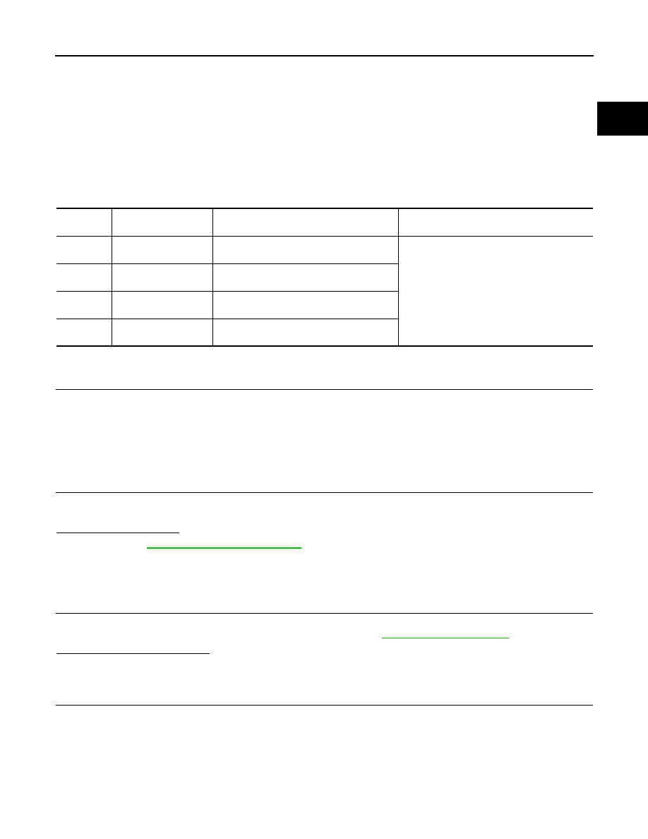
DTC No.
Trouble diagnosis
name
DTC detected condition
Possible cause
P0327
Knock sensor (bank 1)
circuit low input
An excessively low voltage from the sensor is
sent to ECM.
• Harness or connectors
(The sensor circuit is open or shorted.)
• Knock sensor
P0328
Knock sensor (bank 1)
circuit high input
An excessively high voltage from the sensor
is sent to ECM.
P0332
Knock sensor (bank 2)
circuit low input
An excessively low voltage from the sensor is
sent to ECM.
P0333
Knock sensor (bank 2)
circuit high input
An excessively high voltage from the sensor
is sent to ECM.
Нет комментариевНе стесняйтесь поделиться с нами вашим ценным мнением.
Текст