Infiniti EX35. Manual — part 625

EC-242
< COMPONENT DIAGNOSIS >
[VQ35HR]
P0222, P0223, P2132, P2133 TP SENSOR
1.
Replace malfunctioning electric throttle control actuator.
2.
Go to
EC-242, "Special Repair Requirement"
.
>> INSPECTION END
7.
CHECK INTERMITTENT INCIDENT
GI-38, "Intermittent Incident"
>> INSPECTION END
Component Inspection
INFOID:0000000003133403
1.
CHECK THROTTLE POSITION SENSOR
1.
Turn ignition switch OFF.
2.
Reconnect all harness connectors disconnected.
3.
EC-17, "THROTTLE VALVE CLOSED POSITION LEARNING : Special Repair Requirement"
4.
Turn ignition switch ON.
5.
Set selector lever to D position.
6.
Check the voltage between ECM harness connector terminals under the following conditions.
Is the inspection result normal?
YES
>> INSPECTION END
NO
>> GO TO 2.
2.
REPLACE ELECTRIC THROTTLE CONTROL ACTUATOR
1.
Replace malfunctioning electric throttle control actuator.
2.
Go to
EC-242, "Special Repair Requirement"
.
>> INSPECTION END
Special Repair Requirement
INFOID:0000000003133404
1.
PERFORM THROTTLE VALVE CLOSED POSITION LEARNING
EC-17, "THROTTLE VALVE CLOSED POSITION LEARNING : Special Repair Requirement"
>> GO TO 2.
2.
PERFORM IDLE AIR VOLUME LEARNING
EC-18, "IDLE AIR VOLUME LEARNING : Special Repair Requirement"
>> END
ECM
Condition
Voltage (V)
Connector
+
–
Terminal
Terminal
F101
30
[TP sensor 1 (bank 1)]
40
Accelerator pedal : Fully released
More than 0.36
Accelerator pedal : Fully depressed
Less than 4.75
31
[TP sensor 1 (bank 2)]
48
Accelerator pedal : Fully released
More than 0.36
Accelerator pedal : Fully depressed
Less than 4.75
34
[TP sensor 2 (bank 1)]
40
Accelerator pedal : Fully released
Less than 4.75
Accelerator pedal : Fully depressed
More than 0.36
35
[TP sensor 2 (bank 2)]
48
Accelerator pedal : Fully released
Less than 4.75
Accelerator pedal : Fully depressed
More than 0.36

P0300, P0301, P0302, P0303, P0304, P0305, P0306 MISFIRE
EC-243
< COMPONENT DIAGNOSIS >
[VQ35HR]
C
D
E
F
G
H
I
J
K
L
M
A
EC
N
P
O
P0300, P0301, P0302, P0303, P0304, P0305, P0306 MISFIRE
DTC Logic
INFOID:0000000003133405
DTC DETECTION LOGIC
When a misfire occurs, engine speed will fluctuate. If the engine speed fluctuates enough to cause the crank-
shaft position (CKP) sensor (POS) signal to vary, ECM can determine that a misfire is occurring.
The misfire detection logic consists of the following two conditions.
1.
One Trip Detection Logic (Three Way Catalyst Damage)
On the 1st trip that a misfire condition occurs that can damage the three way catalyst (TWC) due to over-
heating, the MIL will blink.
When a misfire condition occurs, the ECM monitors the CKP sensor signal every 200 engine revolutions
for a change.
When the misfire condition decreases to a level that will not damage the TWC, the MIL will turn off.
If another misfire condition occurs that can damage the TWC on a second trip, the MIL will blink.
When the misfire condition decreases to a level that will not damage the TWC, the MIL will remain on.
If another misfire condition occurs that can damage the TWC, the MIL will begin to blink again.
2.
Two Trip Detection Logic (Exhaust quality deterioration)
For misfire conditions that will not damage the TWC (but will affect vehicle emissions), the MIL will only
light when the misfire is detected on a second trip. During this condition, the ECM monitors the CKP sen-
sor signal every 1,000 engine revolutions.
A misfire malfunction can be detected on any one cylinder or on multiple cylinders.
DTC CONFIRMATION PROCEDURE
1.
PRECONDITIONING
If DTC Confirmation Procedure has been previously conducted, always turn ignition switch OFF and wait at
least 10 seconds before conducting the next test.
>> GO TO 2.
2.
PERFORM DTC CONFIRMATION PROCEDURE-I
1.
Start engine and warm it up to normal operating temperature.
2.
Turn ignition switch OFF and wait at least 10 seconds.
3.
Restart engine and let it idle for about 15 minutes.
4.
Check 1st trip DTC.
Is 1st trip DTC detected?
YES
>> Go to
NO
>> GO TO 3.
3.
PERFORM DTC CONFIRMATION PROCEDURE-II
Sensor
Input signal to ECM
ECM function
Crankshaft position sensor (POS)
Engine speed
On board diagnosis of misfire
DTC No.
Trouble diagnosis name
DTC detecting condition
Possible cause
P0300
Multiple cylinder misfire detected
Multiple cylinder misfire.
• Improper spark plug
• Insufficient compression
• Incorrect fuel pressure
• The fuel injector circuit is open or shorted
• Fuel injector
• Intake air leak
• The ignition signal circuit is open or short-
ed
• Lack of fuel
• Signal plate
• A/F sensor 1
• Incorrect PCV hose connection
P0301
No.1 cylinder misfire detected
No. 1 cylinder misfires.
P0302
No. 2 cylinder misfire detected
No. 2 cylinder misfires.
P0303
No. 3 cylinder misfire detected
No. 3 cylinder misfires.
P0304
No. 4 cylinder misfire detected
No. 4 cylinder misfires.
P0305
No. 5 cylinder misfire detected
No. 5 cylinder misfires.
P0306
No. 6 cylinder misfire detected
No. 6 cylinder misfires.

EC-244
< COMPONENT DIAGNOSIS >
[VQ35HR]
P0300, P0301, P0302, P0303, P0304, P0305, P0306 MISFIRE
1.
Turn ignition switch OFF and wait at least 10 seconds.
2.
Start engine and drive the vehicle under the similar conditions to (1st trip) Freeze Frame Data for a certain
time. Refer to the table below.
Hold the accelerator pedal as steady as possible.
The similar conditions to (1st trip) Freeze Frame Data means the vehicle operation that the following con-
ditions should be satisfied at the same time.
CAUTION:
Always drive vehicle in safe manner according to traffic conditions and obey all traffic laws when
driving.
The time to driving varies according to the engine speed in the freeze frame data.
3.
Check 1st trip DTC.
Is 1st trip DTC detected?
YES
>> Go to
NO
>> INSPECTION END
Diagnosis Procedure
INFOID:0000000003133406
1.
CHECK FOR INTAKE AIR LEAK AND PCV HOSE
1.
Start engine and run it at idle speed.
2.
Listen for the sound of the intake air leak.
3.
Check PCV hose connection.
Is intake air leak detected?
YES
>> Discover air leak location and repair.
NO
>> GO TO 2.
2.
CHECK FOR EXHAUST SYSTEM CLOGGING
Stop engine and visually check exhaust tube, three way catalyst and muffler for dents.
Is the inspection result normal?
YES-1 >> With CONSULT-III: GO TO 3.
YES-2 >> Without CONSULT-III: GO TO 4.
NO
>> Repair or replace malfunctioning part.
3.
PERFORM POWER BALANCE TEST
With CONSULT-III
1.
Start engine.
2.
Perform “POWER BALANCE” in “ACTIVE TEST” mode with CONSULT-III.
3.
Check that each circuit produces a momentary engine speed drop.
Is the inspection result normal?
YES
>> GO TO 9.
NO
>> GO TO 4.
4.
CHECK FUNCTION OF FUEL INJECTOR-I
1.
Start engine and let it idle.
Engine speed
Engine speed in the freeze frame data
±
400 rpm
Vehicle speed
Vehicle speed in the freeze frame data
±
10 km/h (6 MPH)
Engine coolant temperature (T)
condition
When the freeze frame data shows lower than 70
°
C (158
°
F),
T should be lower than 70
°
C (158
°
F).
When the freeze frame data shows higher than or equal to 70
°
C (158
°
F),
T should be higher than or equal to 70
°
C (158
°
F).
Engine speed
Time
Around 1,000 rpm
Approximately 10 minutes
Around 2,000 rpm
Approximately 5 minutes
More than 3,000 rpm
Approximately 3.5 minutes
P0300, P0301, P0302, P0303, P0304, P0305, P0306 MISFIRE
EC-245
< COMPONENT DIAGNOSIS >
[VQ35HR]
C
D
E
F
G
H
I
J
K
L
M
A
EC
N
P
O
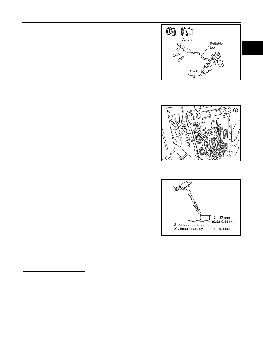
2.
Listen to each fuel injector operating sound.
Is the inspection result normal?
YES
>> GO TO 5.
NO
>> Perform trouble diagnosis for FUEL INJECTOR, refer to
.
5.
CHECK FUNCTION OF IGNITION COIL-I
CAUTION:
Do the following procedure in the place where ventilation is good without the combustible.
1.
Turn ignition switch OFF.
2.
Remove fuel pump fuse (1) in IPDM E/R (2) to release fuel pres-
sure.
NOTE:
Do not use CONSULT-III to release fuel pressure, or fuel pres-
sure applies again during the following procedure.
3.
Start engine.
4.
After engine stalls, crank it two or three times to release all fuel
pressure.
5.
Turn ignition switch OFF.
6.
Remove all ignition coil harness connectors to avoid the electri-
cal discharge from the ignition coils.
7.
Remove ignition coil and spark plug of the cylinder to be
checked.
8.
Crank engine for 5 seconds or more to remove combustion gas in the cylinder.
9.
Connect spark plug and harness connector to ignition coil.
10. Fix ignition coil using a rope etc. with gap of 13 - 17 mm (0.52 -
0.66 in) between the edge of the spark plug and grounded metal
portion as shown in the figure.
11. Crank engine for about 3 seconds, and check whether spark is
generated between the spark plug and the grounded metal por-
tion.
CAUTION:
• Do not approach to the spark plug and the ignition coil
within 50 cm (19.7 in). Be careful not to get an electrical
shock while checking, because the electrical discharge
voltage becomes 20kV or more.
• It might cause to damage the ignition coil if the gap of more than 17 mm (0.66 in) is taken.
NOTE:
When the gap is less than 13 mm (0.52 in), the spark might be generated even if the coil is mal-
functioning.
Is the inspection result normal?
YES
>> GO TO 9.
NO
>> GO TO 6.
6.
CHECK FUNCTION OF IGNITION COIL-II
1.
Turn ignition switch OFF.
2.
Disconnect spark plug and connect a known-good spark plug.
3.
Crank engine for about 3 seconds, and recheck whether spark is generated between the spark plug and
the grounded metal portion.
Clicking sound should be heard.
PBIB3332E
Spark should be generated.
JMBIA0021ZZ
JMBIA0066GB
Spark should be generated.
Нет комментариевНе стесняйтесь поделиться с нами вашим ценным мнением.
Текст