Infiniti EX35. Manual — part 335
C1121, C1123, C1125, C1127 OUT ABS SOL
BRC-55
< COMPONENT DIAGNOSIS >
[VDC/TCS/ABS]
C
D
E
G
H
I
J
K
L
M
A
B
BRC
N
O
P
C1121, C1123, C1125, C1127 OUT ABS SOL
Description
INFOID:0000000003430130
The solenoid valve increases, holds or decreases the fluid pressure of each brake caliper according to the sig-
nals transmitted by the ABS actuator and electric unit (control unit).
DTC Logic
INFOID:0000000003132919
DTC DETECTION LOGIC
DTC CONFIRMATION PROCEDURE
1.
DTC REPRODUCTION PROCEDURE
1.
Turn the ignition switch ON.
2.
Perform ABS actuator and electric unit (control unit) self-diagnosis.
Is DTC “C1121”, “C1123”, “C1125” or “C1127” detected?
YES
>> Proceed to diagnosis procedure. Refer to
.
NO
>> INSPECTION END
Diagnosis Procedure
INFOID:0000000003430131
1.
CHECK CONNECTOR
1.
Turn the ignition switch OFF.
2.
Disconnect ABS actuator and electric unit (control unit) connector.
3.
Check terminal for deformation, disconnection, looseness, etc.
Is the inspection result normal?
YES
>> GO TO 2.
NO
>> Repair or replace damaged parts.
2.
CHECK SOLENOID, VDC SWITCH-OVER VALVE AND ACTUATOR RELAY POWER SUPPLY CIRCUIT
Check the voltage between ABS actuator and electric unit (control unit) harness connector and ground.
Is the inspection result normal?
YES
>> GO TO 3.
NO
>> Repair or replace damaged parts.
3.
CHECK SOLENOID, VDC SWITCH-OVER VALVE AND ACTUATOR RELAY GROUND CIRCUIT
Check the continuity between ABS actuator and electric unit (control unit) harness connector and ground.
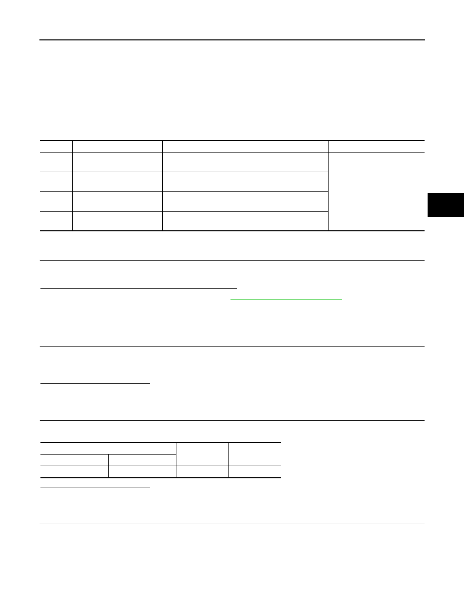
DTC
Display item
Malfunction detected condition
Possible cause
C1121
FR LH OUT ABS SOL
When the control unit detects a malfunction in the front
LH outlet solenoid circuit.
ABS actuator and electric unit
(control unit)
C1123
FR RH OUT ABS SOL
When the control unit detects a malfunction in the front
RH outlet solenoid circuit.
C1125
RR LH OUT ABS SOL
When the control unit detects a malfunction in the rear LH
outlet solenoid circuit.
C1127
RR RH OUT ABS SOL
When the control unit detects a malfunction in the rear
RH outlet solenoid circuit.
ABS actuator and electric unit (control unit)
—
Voltage
Connector
Terminal
E41
3
Ground
Battery voltage
BRC-56
< COMPONENT DIAGNOSIS >
[VDC/TCS/ABS]
C1121, C1123, C1125, C1127 OUT ABS SOL
Is the inspection result normal?
YES
>> Replace ABS actuator and electric unit (control unit).
NO
>> Repair or replace damaged parts.
Component Inspection
INFOID:0000000003430132
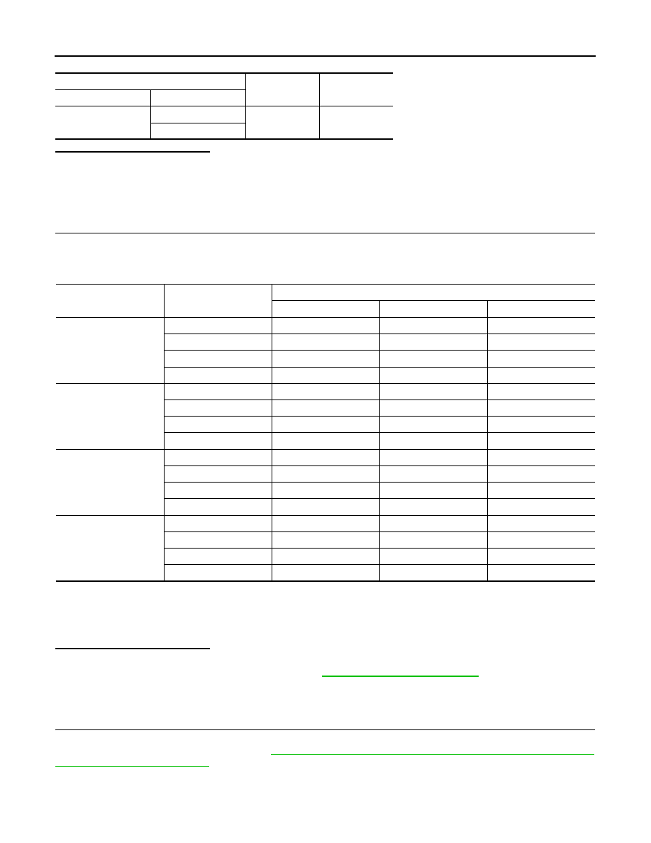
1.
CHECK ACTIVE TEST
1.
Select each test menu item on ”ACTIVE TEST“.
2.
On the display, touch “Up”, “Keep” and “Down”, and check that the system operates as shown in the table
below.
*: On for 1 to 2 seconds after the touch, and then Off.
NOTE:
A brief moment of On/Off condition occurs every 20 seconds after ignition switch turned ON. This is not malfunction because it is
an operation for checking.
Is the inspection result normal?
YES
>> INSPECTION END
NO
>> Proceed to diagnosis procedure. Refer to
.
Special Repair Requirement
INFOID:0000000003430140
1.
ADJUSTMENT OF STEERING ANGLE SENSOR NEUTRAL POSITION
Always perform the neutral position adjustment for the steering angle sensor, when replacing the ABS actua-
tor and electric unit (control unit). Refer to
BRC-8, "ADJUSTMENT OF STEERING ANGLE SENSOR NEU-
>> END
ABS actuator and electric unit (control unit)
—
Continuity
Connector
Terminal
E41
1
Ground
Existed
4
Test item
Display item
Display (Note)
Up
Keep
Down
FR RH SOL
FR RH IN SOL
Off
On
On
FR RH OUT SOL
Off
Off
On*
USV[FR-RL]
Off
Off
Off
HSV[FR-RL]
Off
Off
Off
FR LH SOL
FR LH IN SOL
Off
On
On
FR LH OUT SOL
Off
Off
On*
USV[FL-RR]
Off
Off
Off
HSV[FL-RR]
Off
Off
Off
RR RH SOL
RR RH IN SOL
Off
On
On
RR RH OUT SOL
Off
Off
On*
USV[FL-RR]
Off
Off
Off
HSV[FL-RR]
Off
Off
Off
RR LH SOL
RR LH IN SOL
Off
On
On
RR LH OUT SOL
Off
Off
On*
USV[FR-RL]
Off
Off
Off
HSV[FR-RL]
Off
Off
Off

C1130 ENGINE SIGNAL
BRC-57
< COMPONENT DIAGNOSIS >
[VDC/TCS/ABS]
C
D
E
G
H
I
J
K
L
M
A
B
BRC
N
O
P
C1130 ENGINE SIGNAL
Description
INFOID:0000000003132923
ABS actuator and electric unit (control unit) and ECM exchange the engine signal with CAN communication
line.
DTC Logic
INFOID:0000000003132924
DTC DETECTION LOGIC
DTC CONFIRMATION PROCEDURE
1.
DTC REPRODUCTION PROCEDURE
1.
Turn the ignition switch ON.
2.
Perform ABS actuator and electric unit (control unit) self-diagnosis.
Is DTC “C1130” detected?
YES
>> Proceed to diagnosis procedure. Refer to
.
NO
>> INSPECTION END
Diagnosis Procedure
INFOID:0000000003132925
1.
ECM SELF-DIAGNOSIS
Perform ECM self-diagnosis.
Is any item indicated on the self-diagnosis display?
YES
>> Check the malfunctioning system.
NO
>> GO TO 2.
2.
ABS ACTUATOR AND ELECTRIC UNIT (CONTROL UNIT) SELF-DIAGNOSIS
1.
Erase ABS actuator and electric unit (control unit) self-diagnosis results.
2.
Turn the ignition switch OFF.
3.
Start the engine. Drive the vehicle for a while.
4.
Make sure that malfunction indicator lamp (MIL) turns OFF.
5.
Stop the engine. Perform ABS actuator and electric unit (control unit) self-diagnosis.
Is any item indicated on the self-diagnosis display?
YES
>> Replace ABS actuator and electric unit (control unit).
NO
>> Check ABS actuator and electric unit (control unit) pin terminals for damage or loose connection
with harness connector. If any items and damaged, repair or replace damaged parts.
Special Repair Requirement
INFOID:0000000003430142
1.
ADJUSTMENT OF STEERING ANGLE SENSOR NEUTRAL POSITION
Always perform the neutral position adjustment for the steering angle sensor, when replacing the ABS actua-
tor and electric unit (control unit). Refer to
BRC-8, "ADJUSTMENT OF STEERING ANGLE SENSOR NEU-
>> END
DTC
Display item
Malfunction detected condition
Possible cause
C1130
ENGINE SIGNAL 1
Major engine components are malfunctioning.
• Harness or connector
• ABS actuator and electric unit
(control unit)
• ECM
• CAN communication line

BRC-58
< COMPONENT DIAGNOSIS >
[VDC/TCS/ABS]
C1142 PRESS SENSOR
C1142 PRESS SENSOR
Description
INFOID:0000000003132931
The pressure sensor converts the brake fluid pressure to an electric signal and transmits it to the ABS actuator
and electric unit (control unit). [The pressure sensor is integrated in the ABS actuator and electric unit (control
unit).]
DTC Logic
INFOID:0000000003132932
DTC DETECTION LOGIC
DTC CONFIRMATION PROCEDURE
1.
DTC REPRODUCTION PROCEDURE
1.
Turn the ignition switch ON.
2.
Perform ABS actuator and electric unit (control unit) self-diagnosis.
Is DTC “C1142” detected?
YES
>> Proceed to diagnosis procedure. Refer to
.
NO
>> INSPECTION END
Diagnosis Procedure
INFOID:0000000003132933
1.
CHECK STOP LAMP SWITCH
Check stop lamp switch. Refer to
Is the inspection result normal?
YES
>> GO TO 2.
NO
>> Repair or replace malfunction component.
2.
CHECK DATA MONITOR
Check pressure sensor signal. Refer to
BRC-58, "Component Inspection"
Is the inspection result normal?
YES
>> GO TO 3.
NO
>> • Check brake pedal, brake booster, and master cylinder for mount play, looseness, brake system
fluid leakage, etc.
- Brake pedal: Refer to
BR-7, "Inspection and Adjustment"
.
- Brake booster: Refer to
- Master cylinder: Refer to
.
3.
ABS ACTUATOR AND ELECTRIC UNIT (CONTROL UNIT) SELF-DIAGNOSIS
Perform ABS actuator and electric unit (control unit) self-diagnosis.
Is any item indicated on the self-diagnosis display?
YES
>> Replace ABS actuator and electric unit (control unit).
NO
>> Check ABS actuator and electric unit (control unit) pin terminals for damage or loose connection
with harness connector. If any items are damaged, repair or replace damaged parts.
Component Inspection
INFOID:0000000003132934
1.
CHECK DATA MONITOR
On “DATA MONITOR”, select “PRESS SENSOR” and check the brake fluid pressure.
DTC
Display item
Malfunction detected condition
Possible cause
C1142
PRESS SEN CIRCUIT
Pressure sensor signal line is open or shorted, or pres-
sure sensor is malfunctioning.
• Harness or connector
• Stop lamp switch
• ABS actuator and electric unit
(control unit)
Нет комментариевНе стесняйтесь поделиться с нами вашим ценным мнением.
Текст