Infiniti EX35. Manual — part 334
C1116 STOP LAMP SWITCH
BRC-51
< COMPONENT DIAGNOSIS >
[VDC/TCS/ABS]
C
D
E
G
H
I
J
K
L
M
A
B
BRC
N
O
P
C1116 STOP LAMP SWITCH
Description
INFOID:0000000003132908
The stop lamp switch transmits the stop lamp switch signal (ON/OFF) to the ABS actuator and electric unit
(control unit).
DTC Logic
INFOID:0000000003132909
DTC DETECTION LOGIC
DTC CONFIRMATION PROCEDURE
1.
DTC REPRODUCTION PROCEDURE
1.
Turn the ignition switch ON.
2.
Perform ABS actuator and electric unit (control unit) self-diagnosis.
Is DTC “C1116” detected?
YES
>> Proceed to diagnosis procedure. Refer to
.
NO
>> INSPECTION END
Diagnosis Procedure
INFOID:0000000003132910
1.
CHECK CONNECTOR
1.
Turn the ignition switch OFF.
2.
Disconnect ABS actuator and electric unit (control unit) connector.
3.
Disconnect stop lamp switch connector.
4.
Check terminal for deformation, disconnection, looseness, etc.
Is the inspection result normal?
YES
>> GO TO 2.
NO
>> Repair or replace damaged parts.
2.
CHECK STOP LAMP SWITCH
Check stop lamp switch. Refer to
BRC-51, "Component Inspection"
Is the inspection result normal?
YES
>> GO TO 3.
NO
>> Replace stop lamp switch.
3.
CHECK STOP LAMP SWITCH CIRCUIT
Check the voltage between ABS actuator and electric unit (control unit) harness connector and ground.
Is the inspection result normal?
YES
>> Replace ABS actuator and electric unit (control unit).
NO
>> Repair or replace damaged parts.
Component Inspection
INFOID:0000000003132911
1.
CHECK STOP LAMP SWITCH
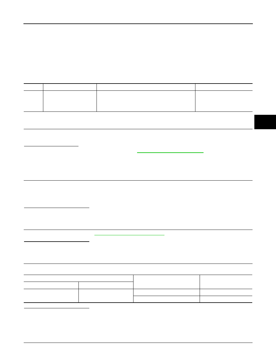
DTC
Display item
Malfunction detected condition
Possible cause
C1116
STOP LAMP SW
When stop lamp switch circuit is open.
• Harness or connector
• Stop lamp switch
• ABS actuator and electric unit
(control unit)
ABS actuator and electric unit (control unit)
Condition
Voltage
Connector
Terminal
E41
30
Brake pedal is depressed
Battery voltage
Brake pedal is released
Approx. 0 V
BRC-52
< COMPONENT DIAGNOSIS >
[VDC/TCS/ABS]
C1116 STOP LAMP SWITCH
1.
Turn the ignition switch OFF.
2.
Disconnect stop lamp switch connector.
3.
Check the continuity between stop lamp switch connector terminals.
Is the inspection result normal?
YES
>> INSPECTION END
NO
>> Replace stop lamp switch. Refer to
.
Special Repair Requirement
INFOID:0000000003430139
1.
ADJUSTMENT OF STEERING ANGLE SENSOR NEUTRAL POSITION
Always perform the neutral position adjustment for the steering angle sensor, when replacing the ABS actua-
tor and electric unit (control unit). Refer to
BRC-8, "ADJUSTMENT OF STEERING ANGLE SENSOR NEU-
>> END
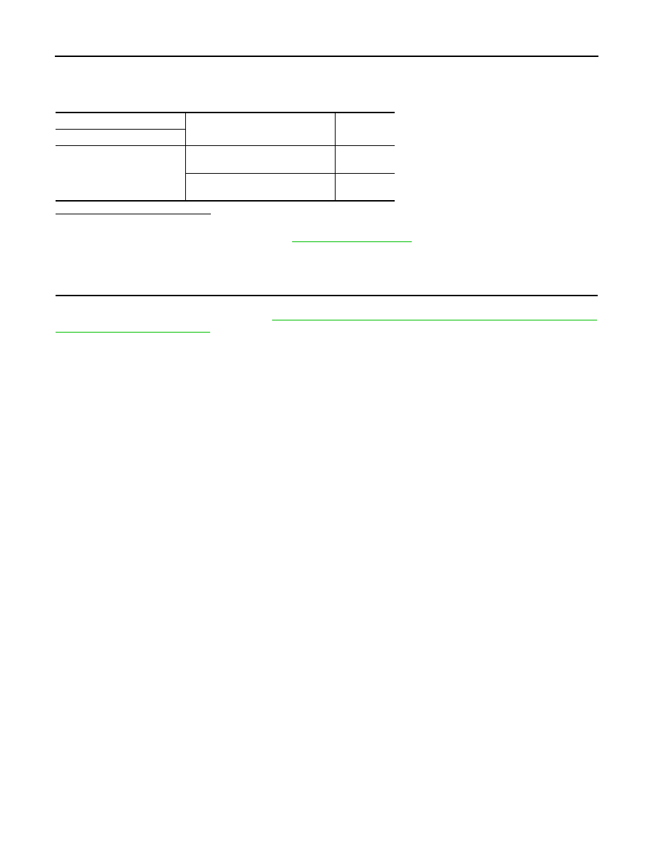
Stop lamp switch
Condition
Continuity
Terminal
1 – 2 (With ICC models)
3
−
4 (Without ICC models)
Release stop lamp switch
(When brake pedal is depressed.)
Existed
Push stop lamp switch
(When brake pedal is released.)
Not existed
C1120, C1122, C1124, C1126 IN ABS SOL
BRC-53
< COMPONENT DIAGNOSIS >
[VDC/TCS/ABS]
C
D
E
G
H
I
J
K
L
M
A
B
BRC
N
O
P
C1120, C1122, C1124, C1126 IN ABS SOL
Description
INFOID:0000000003132913
The solenoid valve increases, holds or decreases the fluid pressure of each brake caliper according to the sig-
nals transmitted by the ABS actuator and electric unit (control unit).
DTC Logic
INFOID:0000000003132914
DTC DETECTION LOGIC
DTC CONFIRMATION PROCEDURE
1.
DTC REPRODUCTION PROCEDURE
1.
Turn the ignition switch ON.
2.
Perform ABS actuator and electric unit (control unit) self-diagnosis.
Is DTC “C1120”, “C1122”, “C1124” or “C1126” detected?
YES
>> Proceed to diagnosis procedure. Refer to
.
NO
>> INSPECTION END
Diagnosis Procedure
INFOID:0000000003132915
1.
CHECK CONNECTOR
1.
Turn the ignition switch OFF.
2.
Disconnect ABS actuator and electric unit (control unit) connector.
3.
Check terminal for deformation, disconnection, looseness, etc.
Is the inspection result normal?
YES
>> GO TO 2.
NO
>> Repair or replace damaged parts.
2.
CHECK SOLENOID, VDC SWITCH-OVER VALVE AND ACTUATOR RELAY POWER SUPPLY CIRCUIT
Check the voltage between ABS actuator and electric unit (control unit) harness connector and ground.
Is the inspection result normal?
YES
>> GO TO 3.
NO
>> Repair or replace damaged parts.
3.
CHECK SOLENOID, VDC SWITCH-OVER VALVE AND ACTUATOR RELAY GROUND CIRCUIT
Check the continuity between ABS actuator and electric unit (control unit) harness connector and ground.
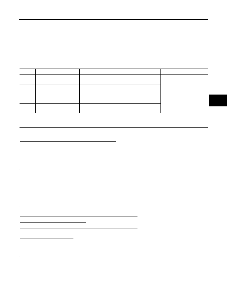
DTC
Display item
Malfunction detected condition
Possible cause
C1120
FR LH IN ABS SOL
When the control unit detects a malfunction in the front
LH inlet solenoid circuit.
ABS actuator and electric unit
(control unit)
C1122
FR RH IN ABS SOL
When the control unit detects a malfunction in the front
RH inlet solenoid circuit.
C1124
RR LH IN ABS SOL
When the control unit detects a malfunction in the rear LH
inlet solenoid circuit.
C1126
RR RH IN ABS SOL
When the control unit detects a malfunction in the rear
RH inlet solenoid circuit.
ABS actuator and electric unit (control unit)
—
Voltage
Connector
Terminal
E41
3
Ground
Battery voltage
BRC-54
< COMPONENT DIAGNOSIS >
[VDC/TCS/ABS]
C1120, C1122, C1124, C1126 IN ABS SOL
Is the inspection result normal?
YES
>> Replace ABS actuator and electric unit (control unit).
NO
>> Repair or replace damaged parts.
Component Inspection
INFOID:0000000003132916
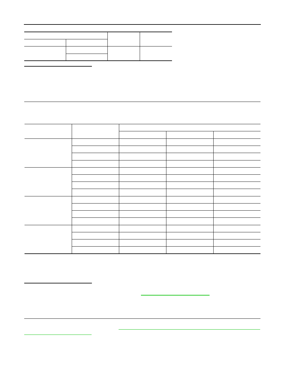
1.
CHECK ACTIVE TEST
1.
Select each test menu item on ”ACTIVE TEST“.
2.
On the display, touch “Up”, “Keep” and “Down”, and check that the system operates as shown in the table
below.
*: On for 1 to 2 seconds after the touch, and then Off.
NOTE:
A brief moment of On/Off condition occurs every 20 seconds after ignition switch turned ON. This is not malfunction because it is
an operation for checking.
Is the inspection result normal?
YES
>> INSPECTION END
NO
>> Proceed to diagnosis procedure. Refer to
.
Special Repair Requirement
INFOID:0000000003430141
1.
ADJUSTMENT OF STEERING ANGLE SENSOR NEUTRAL POSITION
Always perform the neutral position adjustment for the steering angle sensor, when replacing the ABS actua-
tor and electric unit (control unit). Refer to
BRC-8, "ADJUSTMENT OF STEERING ANGLE SENSOR NEU-
>> END
ABS actuator and electric unit (control unit)
—
Continuity
Connector
Terminal
E41
1
Ground
Existed
4
Test item
Display item
Display (Note)
Up
Keep
Down
FR RH SOL
FR RH IN SOL
Off
On
On
FR RH OUT SOL
Off
Off
On*
USV[FR-RL]
Off
Off
Off
HSV[FR-RL]
Off
Off
Off
FR LH SOL
FR LH IN SOL
Off
On
On
FR LH OUT SOL
Off
Off
On*
USV[FL-RR]
Off
Off
Off
HSV[FL-RR]
Off
Off
Off
RR RH SOL
RR RH IN SOL
Off
On
On
RR RH OUT SOL
Off
Off
On*
USV[FL-RR]
Off
Off
Off
HSV[FL-RR]
Off
Off
Off
RR LH SOL
RR LH IN SOL
Off
On
On
RR LH OUT SOL
Off
Off
On*
USV[FR-RL]
Off
Off
Off
HSV[FR-RL]
Off
Off
Off
Нет комментариевНе стесняйтесь поделиться с нами вашим ценным мнением.
Текст