Infiniti EX35. Manual — part 1001
LAN
MAIN LINE BETWEEN AV AND DLC CIRCUIT
LAN-63
< COMPONENT DIAGNOSIS >
[CAN SYSTEM (TYPE 1)]
C
D
E
F
G
H
I
J
K
L
B
A
O
P
N
COMPONENT DIAGNOSIS
MAIN LINE BETWEEN AV AND DLC CIRCUIT
Diagnosis Procedure
INFOID:0000000003515374
INSPECTION PROCEDURE
1.
CHECK HARNESS CONTINUITY (OPEN CIRCUIT)
1.
Turn the ignition switch OFF.
2.
Disconnect the battery cable from the negative terminal.
3.
Disconnect the following harness connectors.
-
ECM
-
AV control unit
4.
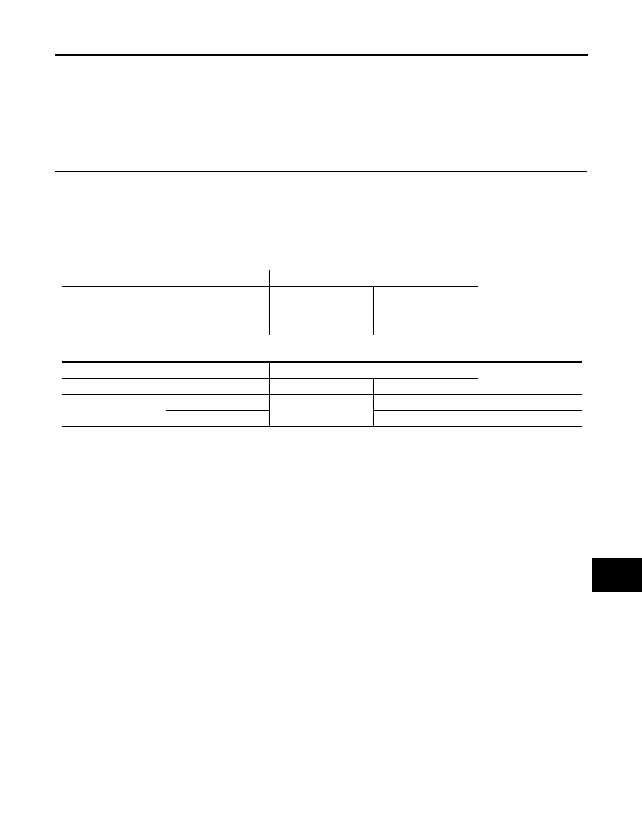
Check the continuity between the AV control unit harness connector and the data link connector.
-
Models with NAVI
-
Models without NAVI
Is the inspection result normal?
YES (Present error)>>Check CAN system type decision again.
YES (Past error)>>Error was detected in the main line between the AV control unit and the data link connec-
tor.
NO
>> Repair the main line between the AV control unit and the data link connector.
AV control unit harness connector
Data link connector
Continuity
Connector No.
Terminal No.
Connector No.
Terminal No.
M87
52
M24
6
Existed
53
14
Existed
AV control unit harness connector
Data link connector
Continuity
Connector No.
Terminal No.
Connector No.
Terminal No.
M85
86
M24
6
Existed
87
14
Existed
LAN-64
< COMPONENT DIAGNOSIS >
[CAN SYSTEM (TYPE 1)]
MAIN LINE BETWEEN DLC AND TCM CIRCUIT
MAIN LINE BETWEEN DLC AND TCM CIRCUIT
Diagnosis Procedure
INFOID:0000000003515376
INSPECTION PROCEDURE
1.
CHECK HARNESS CONTINUITY (OPEN CIRCUIT)
1.
Turn the ignition switch OFF.
2.
Disconnect the battery cable from the negative terminal.
3.
Disconnect the following harness connectors.
-
ECM
-
Harness connectors M116 and F103
4.
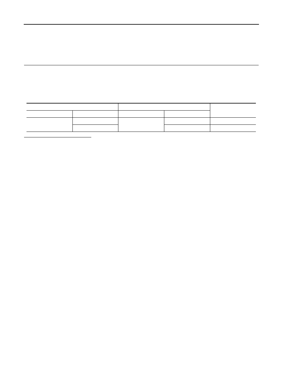
Check the continuity between the data link connector and the harness connector.
Is the inspection result normal?
YES (Present error)>>Check CAN system type decision again.
YES (Past error)>>Error was detected in the main line between the data link connector and the TCM.
NO
>> Repair the main line between the data link connector and the harness connector M116.
Data link connector
Harness connector
Continuity
Connector No.
Terminal No.
Connector No.
Terminal No.
M24
6
M116
44
Existed
14
43
Existed
LAN
MAIN LINE BETWEEN TCM AND ABS CIRCUIT
LAN-65
< COMPONENT DIAGNOSIS >
[CAN SYSTEM (TYPE 1)]
C
D
E
F
G
H
I
J
K
L
B
A
O
P
N
MAIN LINE BETWEEN TCM AND ABS CIRCUIT
Diagnosis Procedure
INFOID:0000000003515377
INSPECTION PROCEDURE
1.
CHECK CONNECTOR
1.
Turn the ignition switch OFF.
2.
Disconnect the battery cable from the negative terminal.
3.
Check the following terminals and connectors for damage, bend and loose connection (connector side
and harness side).
-
Harness connector M6
-
Harness connector E106
Is the inspection result normal?
YES
>> GO TO 2.
NO
>> Repair the terminal and connector.
2.
CHECK HARNESS CONTINUITY (OPEN CIRCUIT)
1.
Disconnect the following harness connectors.
-
Harness connectors F103 and M116
-
Harness connectors M6 and E106
2.
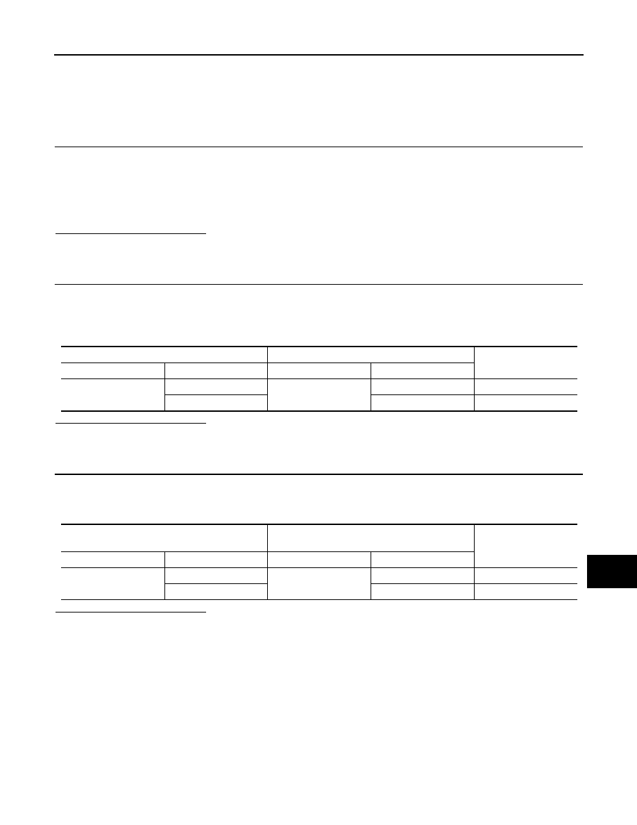
Check the continuity between the harness connectors.
Is the inspection result normal?
YES
>> GO TO 3.
NO
>> Repair the main line between the harness connectors M116 and M6.
3.
CHECK HARNESS CONTINUITY (OPEN CIRCUIT)
1.
Disconnect the connector of ABS actuator and electric unit (control unit).
2.
Check the continuity between the harness connector and the ABS actuator and electric unit (control unit)
harness connector.
Is the inspection result normal?
YES (Present error)>>Check CAN system type decision again.
YES (Past error)>>Error was detected in the main line between the TCM and the ABS actuator and electric
unit (control unit).
NO
>> Repair the main line between the harness connector E106 and the ABS actuator and electric unit
(control unit).
Harness connector
Harness connector
Continuity
Connector No.
Terminal No.
Connector No.
Terminal No.
M116
44
M6
82
Existed
43
81
Existed
Harness connector
ABS actuator and electric unit (control unit)
harness connector
Continuity
Connector No.
Terminal No.
Connector No.
Terminal No.
E106
82
E41
35
Existed
81
14
Existed
LAN-66
< COMPONENT DIAGNOSIS >
[CAN SYSTEM (TYPE 1)]
ECM BRANCH LINE CIRCUIT
ECM BRANCH LINE CIRCUIT
Diagnosis Procedure
INFOID:0000000003515383
1.
CHECK CONNECTOR
1.
Turn the ignition switch OFF.
2.
Disconnect the battery cable from the negative terminal.
3.
Check the terminals and connectors of the ECM for damage, bend and loose connection (unit side and
connector side).
Is the inspection result normal?
YES
>> GO TO 2.
NO
>> Repair the terminal and connector.
2.
CHECK HARNESS FOR OPEN CIRCUIT
1.
Disconnect the connector of ECM.
2.
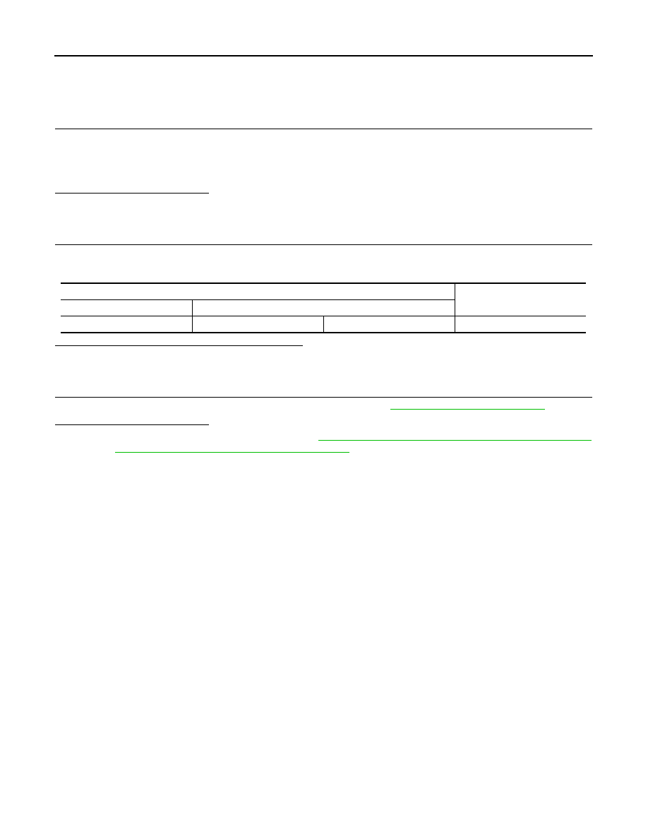
Check the resistance between the ECM harness connector terminals.
Is the measurement value within the specification?
YES
>> GO TO 3.
NO
>> Repair the ECM branch line.
3.
CHECK POWER SUPPLY AND GROUND CIRCUIT
Check the power supply and the ground circuit of the ECM. Refer to
Is the inspection result normal?
YES (Present error)>>Replace the ECM. Refer to
EC-15, "ADDITIONAL SERVICE WHEN REPLACING
CONTROL UNIT : Special Repair Requirement"
.
YES (Past error)>>Error was detected in the ECM branch line.
NO
>> Repair the power supply and the ground circuit.
ECM harness connector
Resistance (
Ω
)
Connector No.
Terminal No.
M107
114
113
Approx. 108 – 132
Нет комментариевНе стесняйтесь поделиться с нами вашим ценным мнением.
Текст