Infiniti EX35. Manual — part 1514

WT-12
< FUNCTION DIAGNOSIS >
DIAGNOSIS SYSTEM (BCM)
The BCM records the following condition at the moment a particular DTC is detected.
• Vehicle Speed
• Odd Trip Meter
• Vehicle Condition (BCM detected condition)
IGN Counter
IGN counter indicates the number of times that ignition switch is turned ON after DTC is detected.
• The number is 0 when a malfunction is detected now.
• The number increases like 1
→
2
→
3...38
→
39 after returning to the normal condition whenever ignition
switch OFF
→
ON.
• The number is fixed to 39 until the self-diagnosis results are erased if it is over 39.
AIR PRESSURE MONITOR
AIR PRESSURE MONITOR : Diagnosis Description
INFOID:0000000003579703
DESCRIPTION
During driving, the TPMS receives the signal transmitted from the transmitter installed in each wheel, when
the tire pressure becomes low. The control unit (BCM) of this system has pressure judgment and trouble diag-
nosis functions.
When the TPMS detects low inflation pressure or another unusual symptom, the low tire pressure warning
lamps in the combination meter comes on.
SELF DIAGNOSTIC PROCEDURE (WITH CONSULT-III)
With CONSULT-III
Touch “SELF-DIAG RESULT” display shows malfunction experienced since the last erasing operation. Refer
to
.
SELF DIAGNOSTIC PROCEDURE (WITHOUT CONSULT-III)
CONSULT screen terms
Description
SLEEP>LOCK
While turning BCM status from low power consumption mode to normal mode (Power supply
position is “LOCK”)
SLEEP>OFF
While turning BCM status from low power consumption mode to normal mode (Power supply
position is “OFF”.)
LOCK>ACC
While turning power supply position from “LOCK” to “ACC”
ACC>ON
While turning power supply position from “ACC” to “IGN”
RUN>ACC
While turning power supply position from “RUN” to “ACC” (Vehicle is stopping and selector
lever is except P position.)
CRANK>RUN
While turning power supply position from “CRANKING” to “RUN” (From cranking up the en-
gine to run it)
RUN>URGENT
While turning power supply position from “RUN“ to “ACC” (Emergency stop operation)
ACC>OFF
While turning power supply position from “ACC” to “OFF”
OFF>LOCK
While turning power supply position from “OFF” to “LOCK”
OFF>ACC
While turning power supply position from “OFF” to “ACC”
ON>CRANK
While turning power supply position from “IGN” to “CRANKING”
OFF>SLEEP
While turning BCM status from normal mode (Power supply position is “OFF”.) to low power
consumption mode
LOCK>SLEEP
While turning BCM status from normal mode (Power supply position is “LOCK”.) to low pow-
er consumption mode
LOCK
Power supply position is “LOCK” (Ignition switch OFF with steering is locked.)
OFF
Power supply position is “OFF” (Ignition switch OFF with steering is unlocked.)
ACC
Power supply position is “ACC” (Ignition switch ACC)
ON
Power supply position is “IGN” (Ignition switch ON with engine stopped)
ENGINE RUN
Power supply position is “RUN” (Ignition switch ON with engine running)
CRANKING
Power supply position is “CRANKING” (At engine cranking)
DIAGNOSIS SYSTEM (BCM)
WT-13
< FUNCTION DIAGNOSIS >
C
D
F
G
H
I
J
K
L
M
A
B
WT
N
O
P
Without CONSULT-III
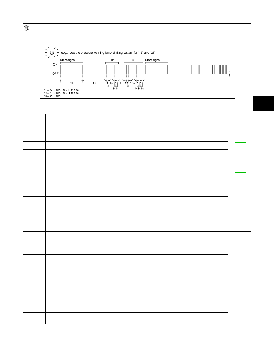
To start the self-diagnostic results mode, ground terminal of the tire pressure warning check connector. The
malfunction location is indicated by the low tire pressure warning lamp blinking.
NOTE:
When the low tire pressure warning lamp blinks 5 Hz and continues repeating it, the system is normal.
JPEIC0030GB
Blinking
pattern
Items
Diagnostic items detected when···
Check item
15
Tire pressure value (Front LH)
Front LH tire pressure drops to * kPa (* kg/cm
2
, * psi) or less. [NOTE]
16
Tire pressure value (Front RH)
Front RH tire pressure drops to * kPa (* kg/cm
2
, * psi) or less. [NOTE]
17
Tire pressure value (Rear RH)
Rear RH tire pressure drops to * kPa (* kg/cm
2
, * psi) or less. [NOTE]
18
Tire pressure value (Rear LH)
Rear LH tire pressure drops to * kPa (* kg/cm
2
, * psi) or less. [NOTE]
21
Transmitter no data (Front LH)
Data from front LH transmitter can not be receive.
22
Transmitter no data (Front RH)
Data from front RH transmitter can not be receive.
23
Transmitter no data (Rear RH)
Data from rear RH transmitter can not be receive.
24
Transmitter no data (Rear LH)
Data from rear LH transmitter can not be receive.
31
Transmitter checksum error
(Front LH)
Checksum data from front LH transmitter is malfunctioning.
32
Transmitter checksum error
(Front RH)
Checksum data from front RH transmitter is malfunctioning.
33
Transmitter checksum error
(Rear RH)
Checksum data from rear RH transmitter is malfunctioning.
34
Transmitter checksum error
(Rear LH)
Checksum data from rear LH transmitter is malfunctioning.
35
Transmitter pressure data error
(Front LH)
Air pressure data from front LH transmitter is malfunction.
36
Transmitter pressure data error
(Front RH)
Air pressure data from front RH transmitter is malfunction.
37
Transmitter pressure data error
(Rear RH)
Air pressure data from rear RH transmitter is malfunction.
38
Transmitter pressure data error
(Rear LH)
Air pressure data from rear LH transmitter is malfunction.
41
Transmitter function code error
(Front LH)
Function code data from front LH transmitter is malfunction.
42
Transmitter function code error
(Front RH)
Function code data from front RH transmitter is malfunction.
43
Transmitter function code error
(Rear RH)
Function code data from rear RH transmitter is malfunction.
44
Transmitter function code error
(Rear LH)
Function code data from rear LH transmitter is malfunction.
WT-14
< FUNCTION DIAGNOSIS >
DIAGNOSIS SYSTEM (BCM)
NOTE:
NOTE: 182.7 kPa (1.9 kg/cm
2
, 26 psi): Standard air pressure is for 230 kPa (2.3 kg/cm
2
, 33 psi) vehicles.
ERASE SELF-DIAGNOSIS
With CONSULT-III
1.
Perform applicable inspection of malfunctioning item and then repair or replace.
2.
Turn ignition switch ON and select “SELF-DIAG RESULTS” mode for “AIR PRESSURE MONITOR” with
CONSULT-III.
3.
Touch “ERASE” on CONSULT-III screen to erase memory.
Without CONSULT-III
• In order to make it easier to find the cause of hard-to-duplicate malfunctions, malfunction information is
stored into the control unit as necessary during use by the user. This memory is not erased no matter how
many times the ignition switch is turned ON and OFF.
• However, this information is erased by turning ignition switch OFF after performing self-diagnostic or by
erasing the memory using the CONSULT-III.
AIR PRESSURE MONITOR : CONSULT-III Function (BCM - AIR PRESSURE MONI-
TOR)
INFOID:0000000003579704
WORK SUPPORT MODE
ID Read
The registered ID number is displayed.
ID Regist
WT-6, "ID REGISTRATION PROCEDURE : Special Repair Requirement"
SELF-DIAG RESULTS MODE
Operation Procedure
.
DATA MONITOR MODE
Screen of data monitor mode is displayed.
NOTE:
When malfunction is detected, CONSULT-III perform REAL-TIME DIAGNOSIS.
Also, any malfunction detected while in this mode will be displayed at real time.
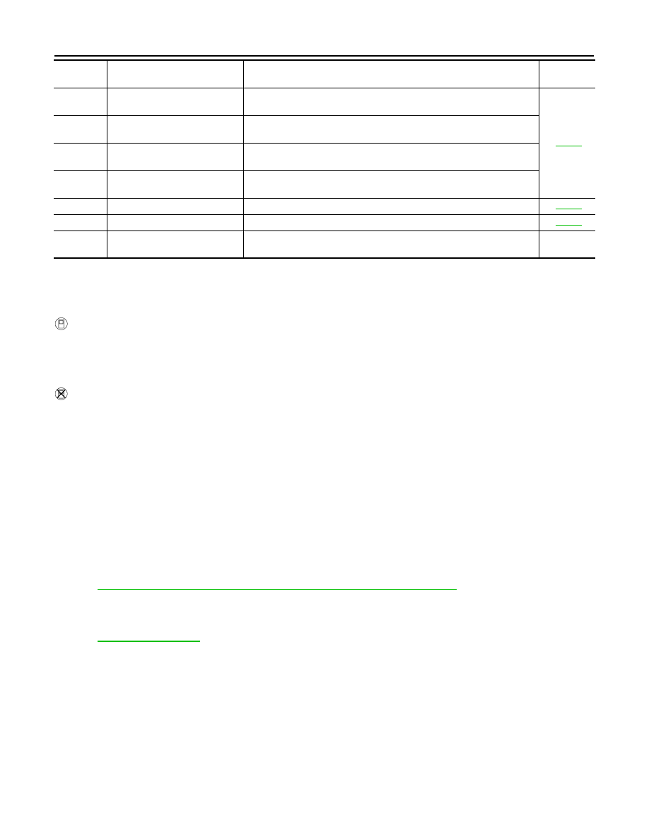
45
Transmitter battery voltage low
(Front LH)
Battery voltage of front LH transmitter drops.
46
Transmitter battery voltage low
(Front RH)
Battery voltage of front RH transmitter drops.
47
Transmitter battery voltage low
(Rear RH)
Battery voltage of rear RH transmitter drops.
48
Transmitter battery voltage low
(Rear LH)
Battery voltage of rear LH transmitter drops.
52
Vehicle speed signal error
Vehicle speed signal error.
53
Control unit
Tire pressure monitoring system malfunction in BCM.
No blinking
Tire pressure warning check
switch
Tire pressure warning switch circuit is open.
–
Blinking
pattern
Items
Diagnostic items detected when···
Check item
DIAGNOSIS SYSTEM (BCM)
WT-15
< FUNCTION DIAGNOSIS >
C
D
F
G
H
I
J
K
L
M
A
B
WT
N
O
P
Display item list
NOTE:
Before performing the self-diagnosis, be sure to register the ID, or erase the actual malfunction location may
be different from that displayed on CONSULT-III.
ACTIVE TEST MODE
NOTE:
Before performing the self-diagnosis, be sure to register the ID, or erase the actual malfunction may be differ-
ent from that displayed on CONSULT-III.
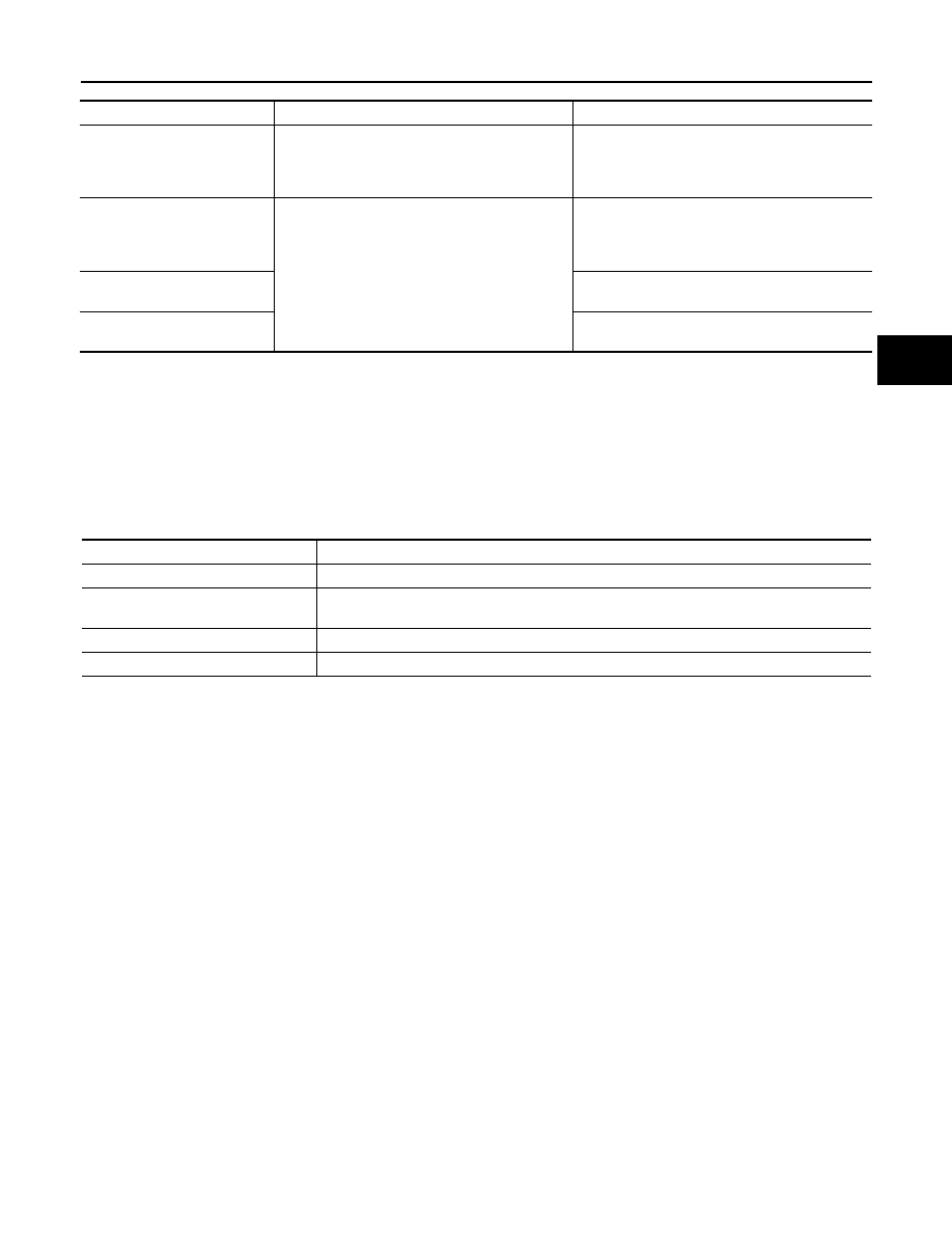
TEST ITEM LIST
Monitor
Condition
Specification
AIR PRESS FL
AIR PRESS FR
AIR PRESS RR
AIR PRESS RL
• Drive vehicle for a few minutes.
or
• Ignition switch ON and transmitter activation
tool is transmitting activation signals.
Tire pressure (kPa, kg/cm
2
or Psi)
ID REGST FL1
ID REGST FR1
ID REGST RR1
ID REGST RL1
Ignition switch ON
Registration ID: Green
No registration: Red
WARNING LAMP
Low tire pressure warning lamp ON: on
Low tire pressure warning lamp OFF: off
BUZZER
Buzzer in combination meter ON: on
Buzzer in combination meter OFF: off
Test item
Content
WARNING LAMP
This test is able to check to check that the low tire pressure warning lamp turns on.
ID REGIST WARNING
This test is able to check to check that the buzzer sounds or the low tire pressure warning lamp
turns on.
FLASHER
This test is able to check to check that each turn signal lamp turns on.
HORN
This test is able to check to check that the horn sounds.
Нет комментариевНе стесняйтесь поделиться с нами вашим ценным мнением.
Текст