Infiniti EX35. Manual — part 1513
WT-8
< FUNCTION DIAGNOSIS >
TPMS
FUNCTION DIAGNOSIS
TPMS
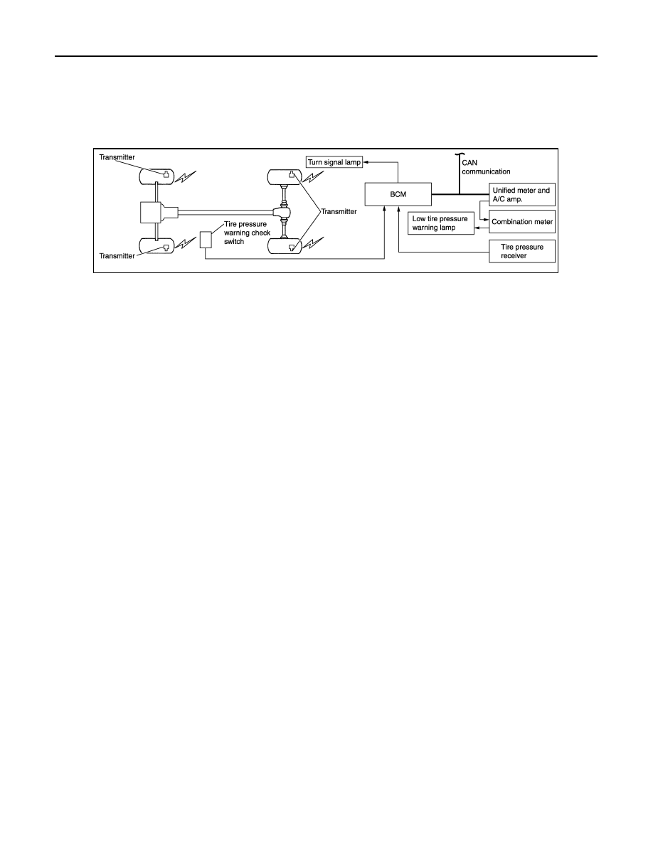
System Diagram
INFOID:0000000003579698
System Description
INFOID:0000000003579699
DESCRIPTION
During driving, the TPMS (Tire Pressure Monitoring System) receives the signal transmitted from transmitter
installed in each wheel. The BCM (Body Control Module) of this system has pressure judgment and trouble
diagnosis functions. When the tire pressure monitoring system detects low inflation pressure or another
unusual symptom, the low tire pressure warning lamps in the combination meter comes on.
JPEIC0054GB
TPMS
WT-9
< FUNCTION DIAGNOSIS >
C
D
F
G
H
I
J
K
L
M
A
B
WT
N
O
P
Component Parts Location
INFOID:0000000003579700
Component Description
INFOID:0000000003579701
1.
Transmitter
2.
BCM
3.
Tire pressure receiver
4.
Tire pressure warning check switch
5.
Low tire pressure warning lamp
A.
Wheel
B.
Dash side lower (passenger side)
C.
Instrument lower panel RH
D.
Behind instrument lower panel LH
E.
Inside combination meter
JPEIC0050ZZ
Component parts
Function
BCM (Body Control Module)
.
Transmitter
.
Tire pressure receiver
.
Tire pressure warning check switch
.
Turn signal lamp
ID registration of each wheel has been completed, turn signal lamp flashes.

WT-10
< FUNCTION DIAGNOSIS >
TPMS
Unified meter and A/C amp.
Transmits the vehicle speed signal via CAN communication to BCM.
Receives the following signals via CAN communication for BCM.
• Tire pressure warning lamp signal
• Hazard lamp signal
• Buzzer signal
Low tire pressure warning lamp
Illuminates if malfunction is detected in electrical system of TPMS.
Component parts
Function

DIAGNOSIS SYSTEM (BCM)
WT-11
< FUNCTION DIAGNOSIS >
C
D
F
G
H
I
J
K
L
M
A
B
WT
N
O
P
DIAGNOSIS SYSTEM (BCM)
COMMON ITEM
COMMON ITEM : CONSULT-III Function (BCM - COMMON ITEM)
INFOID:0000000003774303
APPLICATION ITEM
CONSULT-III performs the following functions via CAN communication with BCM.
SYSTEM APPLICATION
BCM can perform the following functions for each system.
NOTE:
It can perform the diagnosis modes except the following for all sub system selection items.
×
: Applicable item
NOTE:
*: This item is displayed, but is not used.
FREEZE FRAME DATA (FFD) AND IGN COUNTER
Freeze Frame Data
Diagnosis mode
Function Description
Work Support
Changes the setting for each system function.
Self Diagnostic Result
Displays the diagnosis results judged by BCM.
CAN Diag Support Monitor
Monitors the reception status of CAN communication viewed from BCM. Refer to CONSULT-III opera-
tion manual.
Data Monitor
The BCM input/output signals are displayed.
Active Test
The signals used to activate each device are forcibly supplied from BCM.
Ecu Identification
The BCM part number is displayed.
Configuration
• Read and save the vehicle specification.
• Write the vehicle specification when replacing BCM.
System
Sub system selection item
Diagnosis mode
Work Support
Data Monitor
Active Test
Door lock
DOOR LOCK
×
×
×
Rear window defogger
REAR DEFOGGER
×
×
Warning chime
BUZZER
×
×
Interior room lamp timer
INT LAMP
×
×
×
Exterior lamp
HEAD LAMP
×
×
×
Wiper and washer
WIPER
×
×
Turn signal and hazard warning lamps
FLASHER
×
×
×
—
AIR CONDITONER*
• Intelligent Key system
• Engine start system
INTELLIGENT KEY
×
×
×
Combination switch
COMB SW
×
Body control system
BCM
×
IVIS - NATS
IMMU
×
×
Interior room lamp battery saver
BATTERY SAVER
×
×
×
—
TRUNK*
×
×
Vehicle security system
THEFT ALM
×
×
×
RAP system
RETAINED PWR
×
Signal buffer system
SIGNAL BUFFER
×
×
TPMS
TPMS (AIR PRESSURE MONITOR)
×
×
×
Нет комментариевНе стесняйтесь поделиться с нами вашим ценным мнением.
Текст