Infiniti EX35. Manual — part 599
EC-138
< COMPONENT DIAGNOSIS >
[VQ35HR]
P0011, P0021 IVT CONTROL
CAUTION:
Always drive at a safe speed.
3.
Check 1st trip DTC.
With GST
Follow the procedure “With CONSULT-III” above.
Is 1st trip DTC detected?
YES
>> Go to
NO
>> INSPECTION END
Diagnosis Procedure
INFOID:0000000003133298
1.
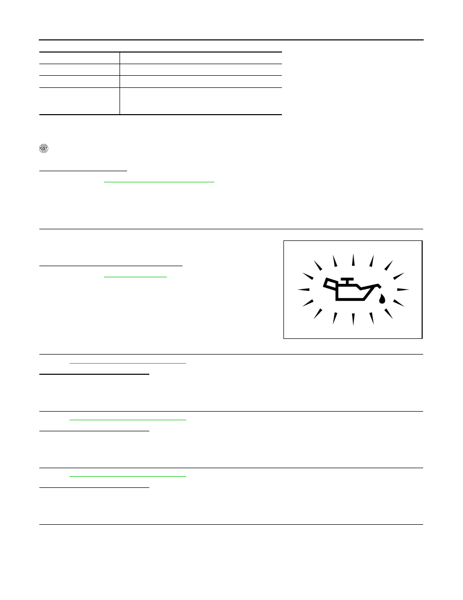
CHECK OIL PRESSURE WARNING LAMP
1.
Start engine.
2.
Check oil pressure warning lamp and confirm it is not illumi-
nated.
Is oil pressure warning lamp illuminated?
YES
>> Go to
.
NO
>> GO TO 2.
2.
CHECK INTAKE VALVE TIMING CONTROL SOLENOID VALVE
EC-139, "Component Inspection"
Is the inspection result normal?
YES
>> GO TO 3.
NO
>> Replace malfunctioning intake valve timing control solenoid valve.
3.
CHECK CRANKSHAFT POSITION SENSOR (POS)
EC-255, "Component Inspection"
Is the inspection result normal?
YES
>> GO TO 4.
NO
>> Replace crankshaft position sensor (POS).
4.
CHECK CAMSHAFT POSITION SENSOR (PHASE)
EC-260, "Component Inspection"
Is the inspection result normal?
YES
>> GO TO 5.
NO
>> Replace malfunctioning camshaft position sensor (PHASE).
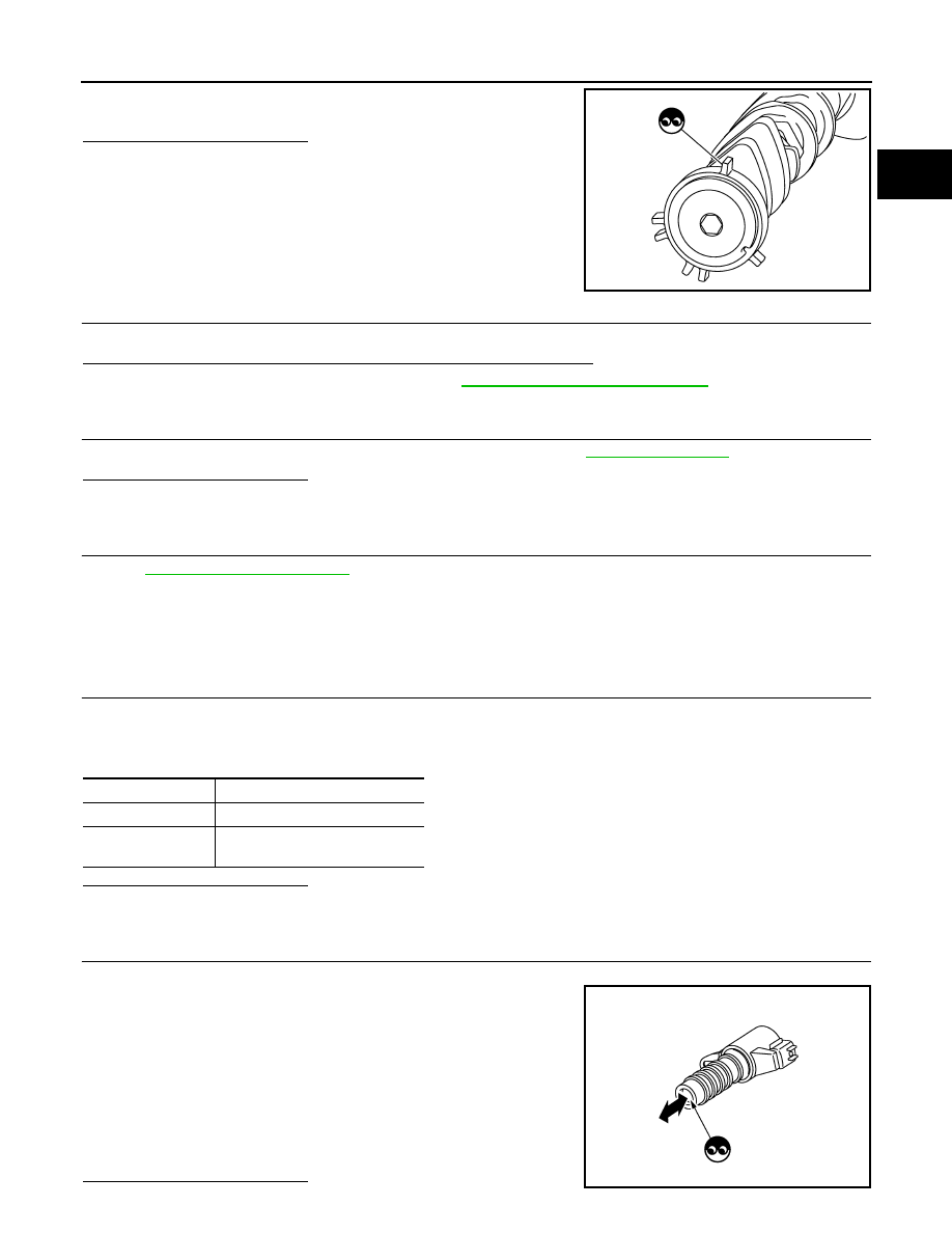
5.
CHECK CAMSHAFT (INTAKE)
Check the following.
ENG SPEED
1,700 - 3,175 rpm (A constant rotation is maintained.)
COOLAN TEMP/S
More than 70
°
C (158
°
F)
Selector lever
1st or 2nd position
Driving location uphill
Driving vehicle uphill
(Increased engine load will help maintain the driving
conditions required for this test.)
PBIA8559J
P0011, P0021 IVT CONTROL
EC-139
< COMPONENT DIAGNOSIS >
[VQ35HR]
C
D
E
F
G
H
I
J
K
L
M
A
EC
N
P
O
• Accumulation of debris to the signal plate of camshaft rear end
• Chipping signal plate of camshaft rear end
Is the inspection result normal?
YES
>> GO TO 6.
NO
>> Remove debris and clean the signal plate of camshaft
rear end or replace camshaft.
6.
CHECK TIMING CHAIN INSTALLATION
Check service records for any recent repairs that may cause timing chain misaligned.
Are there any service records that may cause timing chain misaligned?
YES
>> Check timing chain installation. Refer to
EM-51, "Removal and Installation"
NO
>> GO TO 7.
7.
CHECK LUBRICATION CIRCUIT
Perform “Inspection of Camshaft Sprocket (INT) Oil Groove”. Refer to
Is the inspection result normal?
YES
>> GO TO 8.
NO
>> Clean lubrication line.
8.
CHECK INTERMITTENT INCIDENT
GI-38, "Intermittent Incident"
.
>> INSPECTION END
Component Inspection
INFOID:0000000003133299
1.
CHECK INTAKE VALVE TIMING CONTROL SOLENOID VALVE-I
1.
Turn ignition switch OFF.
2.
Disconnect intake valve timing control solenoid valve harness connector.
3.
Check resistance between intake valve timing control solenoid valve terminals as follows.
Is the inspection result normal?
YES
>> GO TO 2.
NO
>> Replace malfunctioning intake valve timing control solenoid valve.
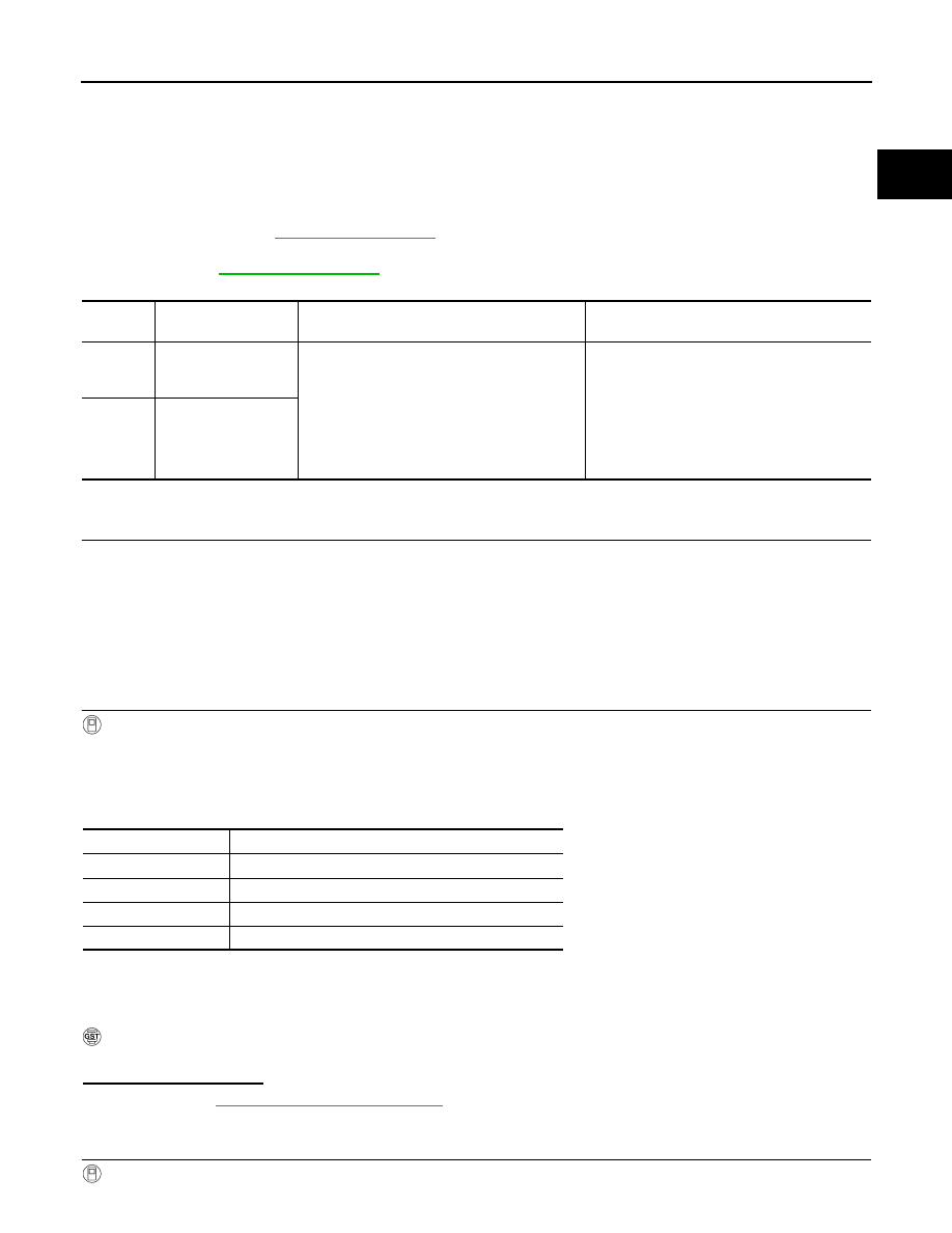
2.
CHECK INTAKE VALVE TIMING CONTROL SOLENOID VALVE-II
1.
Remove intake valve timing control solenoid valve.
2.
Provide 12 V DC between intake valve timing control solenoid
valve terminals 1 and 2, and then interrupt it. Check that the
plunger moves as shown in the figure.
CAUTION:
Do not apply 12 V DC continuously for 5 seconds or more.
Doing so may result in damage to the coil in intake valve
timing control solenoid valve.
NOTE:
Always replace O-ring when intake valve timing control
solenoid valve is removed.
Is the inspection result normal?
JMBIA0058ZZ
Terminals
Resistance
1 and 2
7.0 - 7.7
Ω
[at 20
°
C (68
°
F)]
1 or 2 and ground
∞Ω
(Continuity should not exist)
JMBIA0079ZZ
EC-140
< COMPONENT DIAGNOSIS >
[VQ35HR]
P0011, P0021 IVT CONTROL
YES
>> INSPECTION END
NO
>> Replace malfunctioning intake valve timing control solenoid valve.
P0014, P0024 EVT CONTROL
EC-141
< COMPONENT DIAGNOSIS >
[VQ35HR]
C
D
E
F
G
H
I
J
K
L
M
A
EC
N
P
O
P0014, P0024 EVT CONTROL
DTC Logic
INFOID:0000000003133300
DTC DETECTION LOGIC
NOTE:
• If DTC P0014 or P0024 is displayed with DTC P0078, P0084 first perform trouble diagnosis for DTC
P0078, P0084. Refer to
.
• If DTC P0014 or P0024 is displayed with P1078, P1084 first perform trouble diagnosis for P1078,
P1084. Refer to
.
DTC CONFIRMATION PROCEDURE
1.
PRECONDITIONING
If DTC Confirmation Procedure has been previously conducted, always turn ignition switch OFF and wait at
least 10 seconds before conducting the next test.
TESTING CONDITION:
Before performing the following procedure, confirm that battery voltage is between 10V and 16V at
idle.
>> GO TO 2.
2.
PERFORM DTC CONFIRMATION PROCEDURE-I
With CONSULT-III
1.
Turn ignition switch ON and select “DATA MONITOR” mode with CONSULT-III.
2.
Start engine and warm it up to the normal operating temperature.
3.
Maintain the following conditions for at least 6 consecutive seconds.
Hold the accelerator pedal as steady as possible.
CAUTION:
Always drive at a safe speed.
4.
Let engine idle for 10 seconds.
5.
Check 1st trip DTC.
With GST
Follow the procedure “With CONSULT-III” above.
Is 1st trip DTC detected?
YES
>> Go to
NO
>> GO TO 3.
3.
PERFORM DTC CONFIRMATION PROCEDURE-II
With CONSULT-III
DTC No.
Trouble diagnosis
name
Detecting condition
Possible cause
P0014
Exhaust valve timing
control performance
(bank 1)
There is a gap between angle of target and
phase-control angle degree.
• Crankshaft position sensor (POS)
• Camshaft position sensor (PHASE)
• Exhaust valve timing control position sensor
• Exhaust valve control magnet retarder
• Accumulation of debris to the signal pick-up
portion of the camshaft
• Timing chain installation
• Exhaust valve timing control pulley assembly
P0024
Exhaust valve timing
control performance
(bank 2)
VHCL SPEED SE
100 - 120 km/h (63 - 75 mph)
ENG SPEED
1,200 - 2,000 rpm (A constant rotation is maintained.)
COOLAN TEMP/S
More than 60
°
C (140
°
F)
B/FUEL SCHDL
More than 7.3 msec
Selector lever
D position
Нет комментариевНе стесняйтесь поделиться с нами вашим ценным мнением.
Текст