Infiniti EX35. Manual — part 519
DLN-26
< ECU DIAGNOSIS >
[TRANSFER: ETX13B]
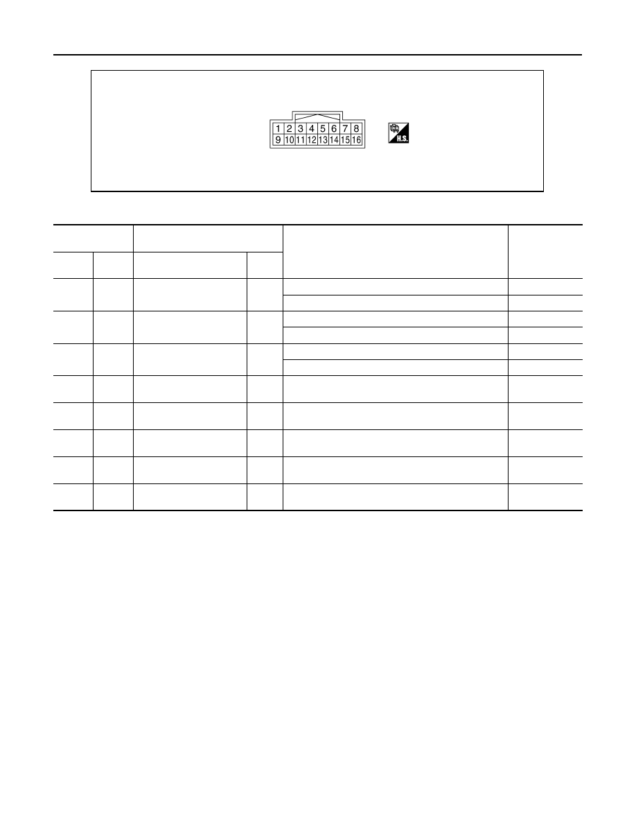
AWD CONTROL UNIT
PHYSICAL VALUES
*: The values are changed by throttle opening and engine speed.
CAUTION:
When using circuit tester to measure voltage for inspection, be sure not to extend forcibly any connector terminals.
JSDIA0057ZZ
Terminal No.
(Wire color)
Description
Condition
Value (Approx.)
+
-
Signal name
Input/
Output
1
(BR)
Ground
AWD solenoid power sup-
ply
Output
Engine speed: At idle
0 V
Engine speed: 3,000 rpm or more constant
2.5 V*
2
(Y)
Ground
AWD solenoid ground
—
Engine speed: At idle
0 V
Engine speed: 3,000 rpm or more constant
0 V
7
(G)
Ground
Ignition switch
Input
Ignition switch: ON
Battery voltage
Ignition switch: OFF
0 V
8
(L)
—
CAN-H
Input/
Output
—
—
9
(O)
Ground
Power supply (AWD sole-
noid)
Input
Always
Battery voltage
10
(B)
Ground
Ground
—
Always
0 V
11
(B)
Ground
Ground
—
Always
0 V
16
(P)
—
CAN-L
Input/
Output
—
—
AWD CONTROL UNIT
DLN-27
< ECU DIAGNOSIS >
[TRANSFER: ETX13B]
C
E
F
G
H
I
J
K
L
M
A
B
DLN
N
O
P
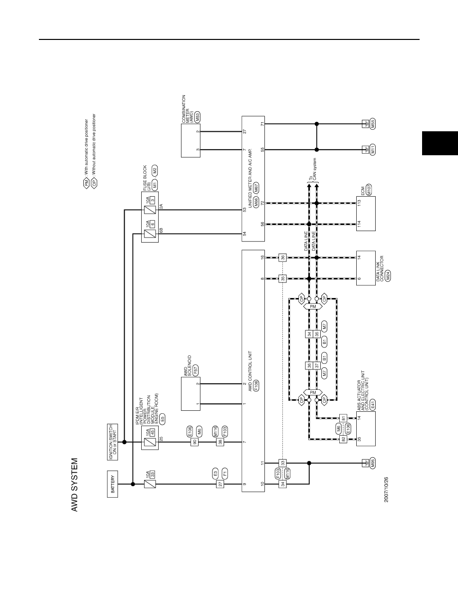
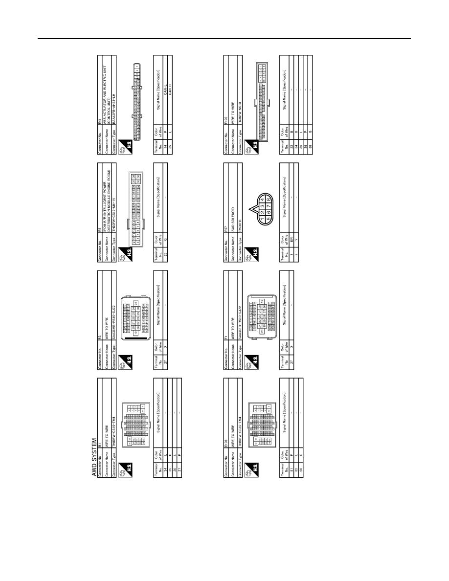
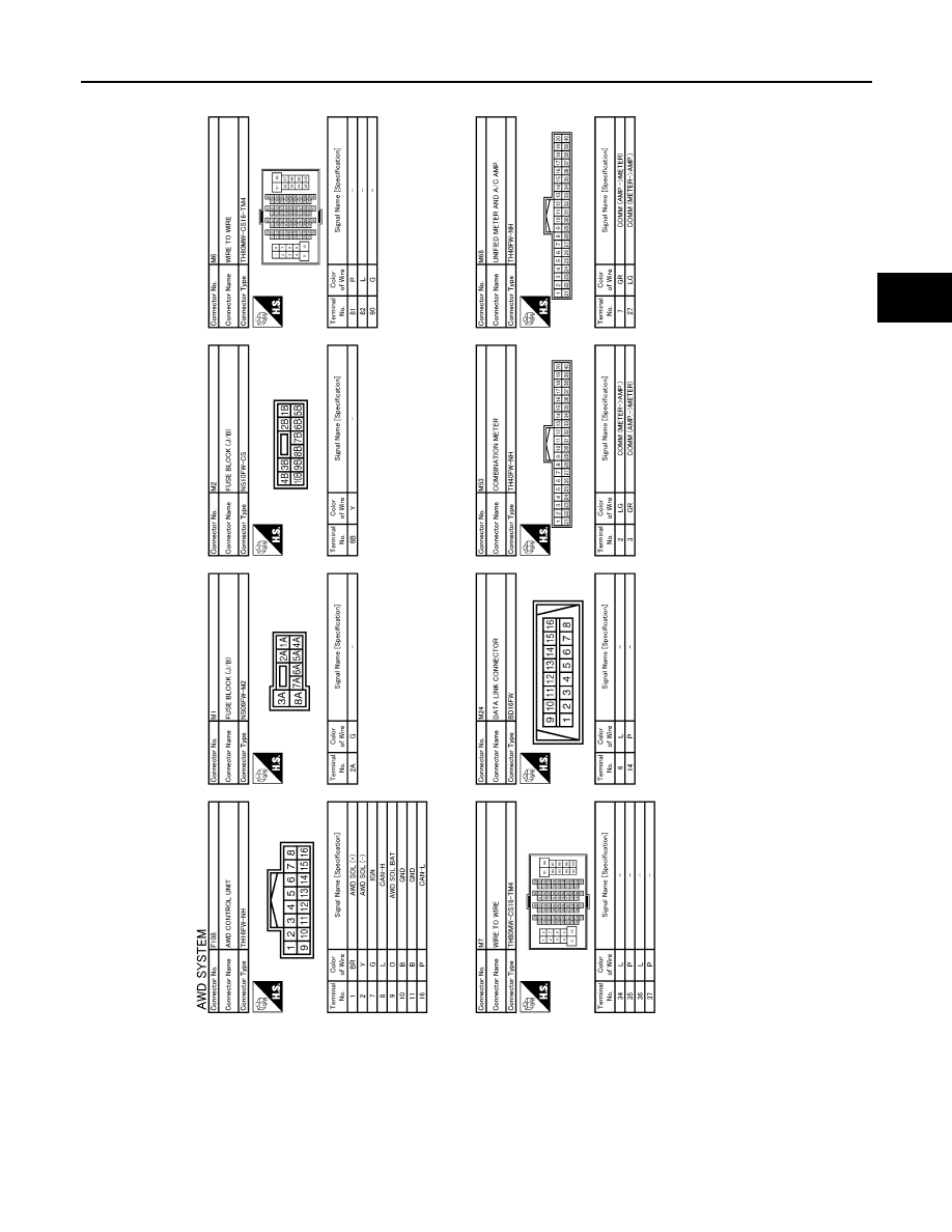
Wiring Diagram - AWD SYSTEM -
INFOID:0000000003135694
JCDWM0204GB
DLN-28
< ECU DIAGNOSIS >
[TRANSFER: ETX13B]
AWD CONTROL UNIT
JCDWM0205GB
AWD CONTROL UNIT
DLN-29
< ECU DIAGNOSIS >
[TRANSFER: ETX13B]
C
E
F
G
H
I
J
K
L
M
A
B
DLN
N
O
P
JCDWM0206GB
Нет комментариевНе стесняйтесь поделиться с нами вашим ценным мнением.
Текст