Infiniti EX35. Manual — part 114

AV
COMPOSITE IMAGE SIGNAL CIRCUIT
AV-237
< COMPONENT DIAGNOSIS >
[BOSE AUDIO WITHOUT NAVIGATION]
C
D
E
F
G
H
I
J
K
L
M
B
A
O
P
COMPOSITE IMAGE SIGNAL CIRCUIT
Description
INFOID:0000000003544789
AV control unit that inputs the camera image signal and AUX image signal transmits the composite image sig-
nal to the display unit.
Diagnosis Procedure
INFOID:0000000003544790
1.
CHECK CONTINUITY COMPOSITE IMAGE SIGNAL CIRCUIT (AV CONTROL UNIT TO DISPLAY UNIT)
1.
Turn ignition switch OFF.
2.
Disconnect AV control unit connector and display unit connector.
3.
Check continuity between AV control unit harness connector and display unit harness connector.
4.
Check continuity between AV control unit harness connector and ground.
Is inspection result normal?
YES
>> GO TO 2.
NO
>> Repair harness or connector.
2.
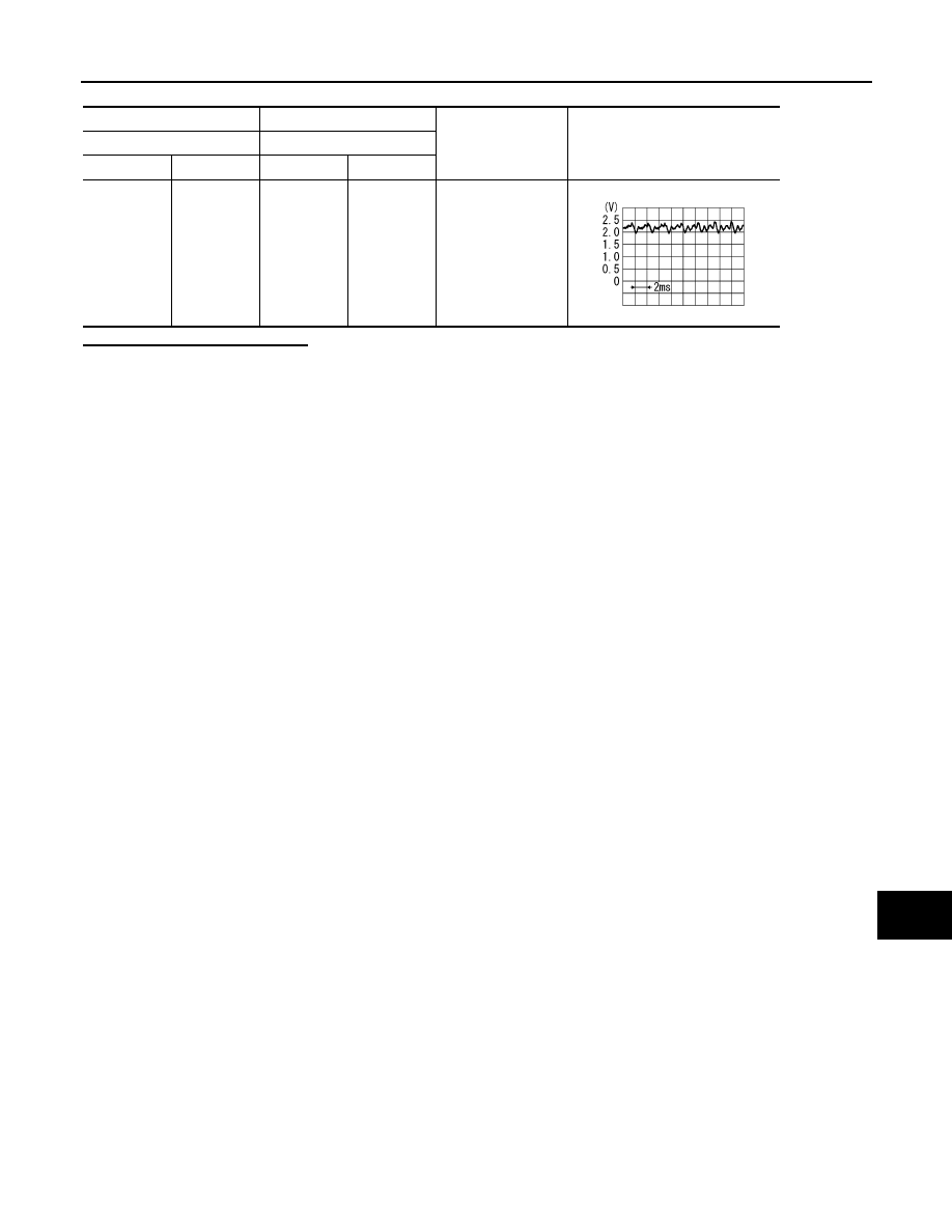
CHECK COMPOSITE IMAGE SIGNAL (AV CONTROL UNIT TO DISPLAY UNIT)
1.
Connect AV control unit connector and display unit connector.
2.
Turn ignition switch ON.
3.
Check signal between AV control unit harness connector and ground.
Is inspection result normal?
YES
>> Replace display unit.
NO
>> Replace AV control unit.
AV control unit
Display unit
Continuity
Connector
Terminal
Connector
Terminal
M83
36
M71
15
Existed
AV control unit
Ground
Continuity
Connector
Terminal
M83
36
Not existed
(+)
(
−
)
Condition
Reference value
AV control unit
Connector
Terminal
M83
36
Ground
At rear view camera or AUX
image is displayed.
SKIB2251J

AV-238
< COMPONENT DIAGNOSIS >
[BOSE AUDIO WITHOUT NAVIGATION]
MICROPHONE SIGNAL CIRCUIT
MICROPHONE SIGNAL CIRCUIT
Description
INFOID:0000000003508710
Supply power from TEL adapter unit to microphone. The microphone transmits the sound/voice to the micro-
phone.
Diagnosis Procedure
INFOID:0000000003508711
1.
CHECK CONTINUITY BETWEEN TEL ADAPTER UNIT AND MICROPHONE CIRCUIT
1.
Turn ignition switch OFF.
2.
Disconnect TEL adapter unit connector and microphone connector.
3.
Check continuity between TEL adapter unit harness connector and microphone harness connector.
4.
Check continuity between TEL adapter unit harness connector and ground.
Is the inspection result normal?
YES
>> GO TO 2.
NO
>> Repair harness or connector.
2.
CHECK VOLTAGE MICROPHONE VCC
1.
Connect TEL adapter unit connector.
2.
Turn ignition switch ON.
3.
Check voltage between TEL adapter unit harness connector.
Is the inspection result normal?
YES
>> GO TO 3.
NO
>> Replace TEL adapter unit.
3.
CHECK MICROPHONE SIGNAL
1.
Turn ignition switch OFF.
2.
Connect microphone connector.
3.
Turn ignition switch ON.
4.
Check signal between TEL adapter unit harness connector.
TEL adapter unit
Microphone
Continuity
Connector
Terminals
Connector
Terminals
B237
7
R17
1
Existed
8
2
29
4
TEL adapter unit
Ground
Continuity
Connector
Terminals
B237
7
Not existed
29
(+)
(
−
)
Voltage
(Approx.)
TEL adapter unit
TEL adapter unit
Connector
Terminal
Connector
Terminal
B237
29
B237
8
5.0 V
AV
MICROPHONE SIGNAL CIRCUIT
AV-239
< COMPONENT DIAGNOSIS >
[BOSE AUDIO WITHOUT NAVIGATION]
C
D
E
F
G
H
I
J
K
L
M
B
A
O
P
Is the inspection result normal?
YES
>> Replace TEL adapter unit.
NO
>> Replace microphone.
(+)
(
−
)
Condition
Reference value
TEL adapter unit
TEL adapter unit
Connector
Terminal
Connector
Terminal
B237
7
B237
8
Give a voice.
PKIB5037J

AV-240
< COMPONENT DIAGNOSIS >
[BOSE AUDIO WITHOUT NAVIGATION]
CONTROL SIGNAL CIRCUIT
CONTROL SIGNAL CIRCUIT
Description
INFOID:0000000003508712
TEL adapter unit identifies the vehicle model according to the control signal and performs the control.
Diagnosis Procedure
INFOID:0000000003508713
1.
CHECK CONTINUITY CONTROL SIGNAL CIRCUIT
1.
Turn ignition switch OFF.
2.
Disconnect TEL adapter unit connector.
3.
Check continuity between TEL adapter unit harness connector and ground.
Is the inspection result normal?
YES
>> Replace TEL adapter unit.
NO
>> Repair harness or connector.
TEL adapter unit
Ground
Continuity
Connector
Terminals
B237
22
Existed
23
24
Нет комментариевНе стесняйтесь поделиться с нами вашим ценным мнением.
Текст