Infiniti EX35. Manual — part 115
AV
MODE CHANGE SIGNAL CIRCUIT
AV-241
< COMPONENT DIAGNOSIS >
[BOSE AUDIO WITHOUT NAVIGATION]
C
D
E
F
G
H
I
J
K
L
M
B
A
O
P
MODE CHANGE SIGNAL CIRCUIT
Description
INFOID:0000000003508714
• AV control unit transmits the mode change signal to BOSE amp.
• Driver's Audio Stage controls the speaker's output characteristic by BOSE amp. so that the driver's seat is to
be the center of sounds.
Diagnosis Procedure
INFOID:0000000003508715
1.
CHECK CONTINUITY MODE CHANGE SIGNAL CIRCUIT
1.
Turn ignition switch OFF.
2.
Disconnect BOSE amp. connector and AV control unit connector.
3.
Check continuity between BOSE amp. harness connector and AV control unit harness connector.
4.
Check continuity between BOSE amp. harness connector and ground.
Is the inspection result normal?
YES
>> GO TO 2.
NO
>> Repair harness or connector.
2.
CHECK MODE CHANGE SIGNAL
1.
Connect BOSE amp. connector.
2.
Turn ignition switch ON.
3.
Check signal between BOSE amp. harness connector and ground.
Is the inspection result normal?
YES
>> Replace AV control unit.
NO
>> Replace BOSE amp.
BOSE amp.
AV control unit
Continuity
Connector
Terminal
Connector
Terminal
B41
17
M82
27
Existed
BOSE amp.
Ground
Continuity
Connector
Terminal
B41
17
Not existed
(+)
(
−
)
Reference value
(Approx.)
BOSE amp.
Connector
Terminal
B41
17
Ground
8.5 V
AV-242
< COMPONENT DIAGNOSIS >
[BOSE AUDIO WITHOUT NAVIGATION]
COMMUNICATION SIGNAL CIRCUIT (CONT-SAT)
COMMUNICATION SIGNAL CIRCUIT (CONT-SAT)
Description
INFOID:0000000003544791
Satellite radio tuner and AV control unit are connected with a serial communication. They transmit the opera-
tion signal from AV control unit to satellite radio tuner, and transmit the display signal from satellite radio tuner
to AV control unit.
Diagnosis Procedure
INFOID:0000000003544792
1.
CHECK CONTINUITY COMMUNICATION SIGNAL CIRCUIT
1.
Turn ignition switch OFF.
2.
Disconnect satellite radio tuner connector and AV control unit connector.
3.
Check continuity between satellite radio tuner harness connector and AV control unit harness connector.
4.
Check continuity between satellite radio tuner harness connector and ground.
Is the inspection result normal?
YES
>> GO TO 2.
NO
>> Repair harness or connector.
2.
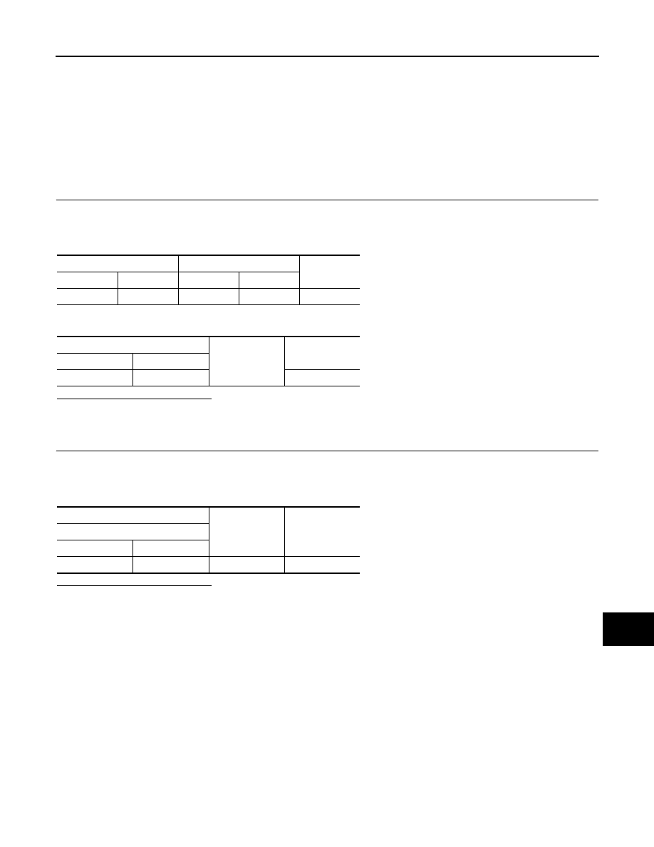
CHECK COMMUNICATION SIGNAL (SAT
→
CONT)
1.
Connect satellite radio tuner connector and AV control unit connector.
2.
Turn ignition switch ON.
3.
Check signal between satellite radio tuner harness connector and ground.
Is the inspection result normal?
YES
>> GO TO 3.
NO
>> Replace satellite radio tuner.
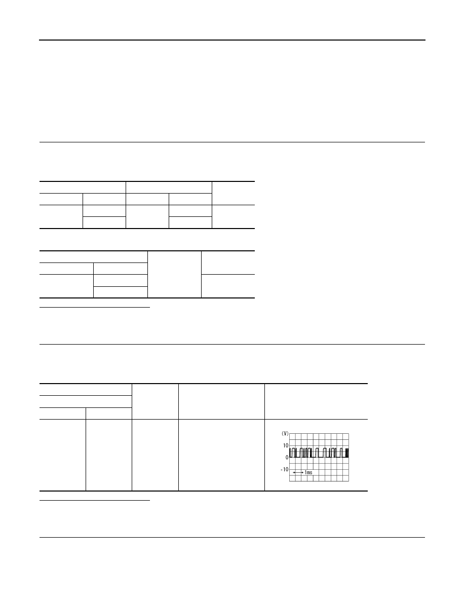
3.
CHECK COMMUNICATION SIGNAL (CONT
→
SAT)
Check signal between satellite radio tuner harness connector and ground.
Satellite radio tuner
AV control unit
Continuity
Connector
Terminals
Connector
Terminals
B236
9
M82
29
Existed
10
30
Satellite radio tuner
Ground
Continuity
Connector
Terminals
B236
9
Not existed
10
(+)
(
−
)
Condition
Reference value
Satellite radio tuner
Connector
Terminal
B236
9
Ground
When satellite radio mode is
selected.
SKIA9300J
AV
COMMUNICATION SIGNAL CIRCUIT (CONT-SAT)
AV-243
< COMPONENT DIAGNOSIS >
[BOSE AUDIO WITHOUT NAVIGATION]
C
D
E
F
G
H
I
J
K
L
M
B
A
O
P
Is the inspection result normal?
YES
>> Replace satellite radio tuner.
NO
>> Replace AV control unit.
(+)
(
−
)
Condition
Reference value
Satellite radio tuner
Connector
Terminal
B236
10
Ground
When satellite radio mode is
selected.
SKIA9301J
AV-244
< COMPONENT DIAGNOSIS >
[BOSE AUDIO WITHOUT NAVIGATION]
REQUEST SIGNAL CIRCUIT (SAT
→
CONT)
REQUEST SIGNAL CIRCUIT (SAT
→
CONT)
Description
INFOID:0000000003544793
Request signal transmits the signal to recognize the connection of satellite radio tuner from satellite radio
tuner to AV control unit.
Diagnosis Procedure
INFOID:0000000003544794
1.
CHECK CONTINUITY REQUEST SIGNAL CIRCUIT
1.
Turn ignition switch OFF.
2.
Disconnect satellite radio tuner connector and AV control unit connector.
3.
Check continuity between satellite radio tuner unit harness connector and AV control unit harness connec-
tor.
4.
Check continuity between satellite radio tuner harness connector and ground.
Is the inspection result normal?
YES
>> GO TO 2.
NO
>> Repair harness or connector.
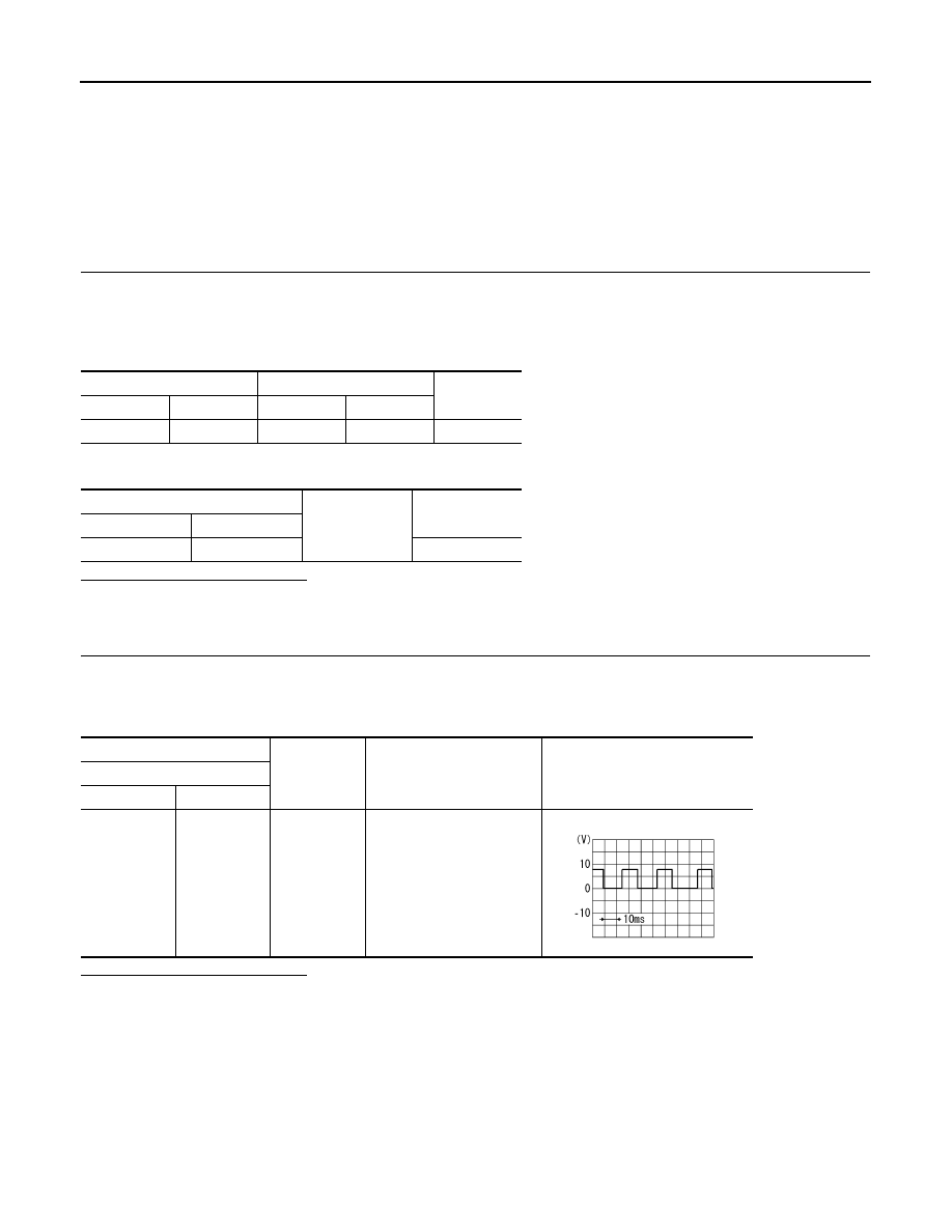
2.
CHECK COMMUNICATION SIGNAL
1.
Connect satellite radio tuner connector and AV control unit connector.
2.
Turn ignition switch ON.
3.
Check signal between satellite radio tuner harness connector and ground.
Is the inspection result normal?
YES
>> Replace AV control unit.
NO
>> Replace satellite radio tuner.
Satellite radio tuner
AV control unit
Continuity
Connector
Terminal
Connector
Terminal
B236
8
M82
28
Existed
Satellite radio tuner
Ground
Continuity
Connector
Terminal
B236
8
Not existed
(+)
(
−
)
Condition
Reference value
Satellite radio tuner
Connector
Terminal
B236
8
Ground
When satellite radio mode is
selected.
SKIA9299J
Нет комментариевНе стесняйтесь поделиться с нами вашим ценным мнением.
Текст