Infiniti EX35. Manual — part 170
AV
NAVIGATION SYSTEM
AV-461
< FUNCTION DIAGNOSIS >
[BOSE AUDIO WITH NAVIGATION]
C
D
E
F
G
H
I
J
K
L
M
B
A
O
P
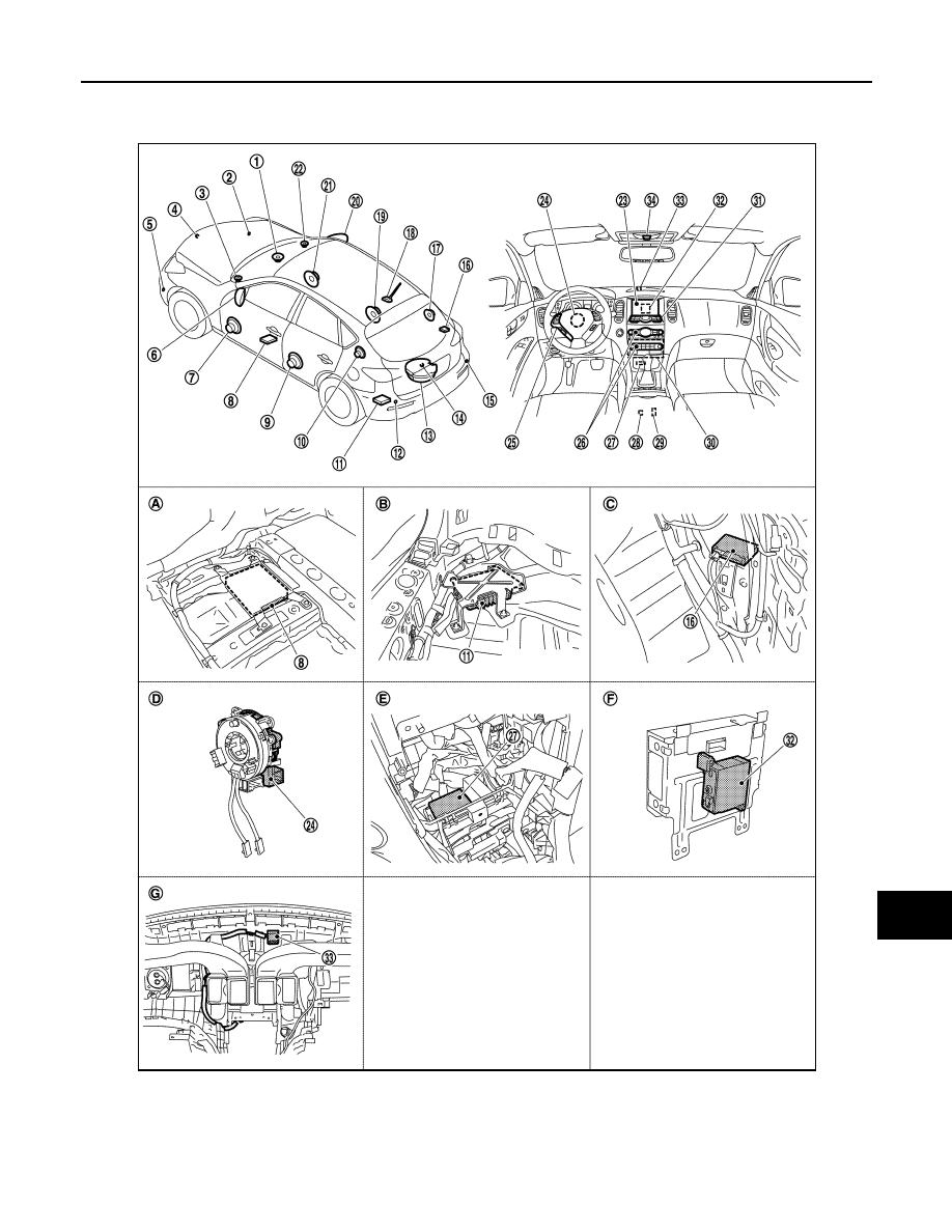
Component Parts Location
INFOID:0000000003579817
1.
Center speaker
2.
Corner sensor front RH
3.
Front squawker LH
4.
Front camera
5.
Corner sensor front LH
6.
Side camera LH
JPNIA0911ZZ

A
V
- 4
6
2
< FUNCTION DIAGNOSIS >
[BOSE AUDIO WITH NAVIGATION]
NAVIGATION SYSTEM
Component Description
INFOID:0000000003515972
7.
Front door speaker LH
8.
• Around view monitor control unit
(with around view monitor)
• Camera control unit (with rear view
monitor)
9.
Rear door speaker LH
10. Rear squawker LH
11. BOSE amp.
12. Corner sensor rear LH
13. Woofer
14. • Rear camera (with around view
monitor)
• Rear view camera (with rear view
monitor)
15. Corner sensor rear RH
16. Buzzer
17. Rear squawker RH
18. Antenna base (antenna amp and sat-
ellite antenna)
19. Rear door speaker RH
20. Side camera RH
21. Front door speaker RH
22. Front squawker RH
23. Display unit
24. Steering angle sensor
25. Steering switch
26. Preset switch
27. Sonar control unit (with around view
monitor)
28. iPod connector
29. Auxiliary input jacks
30. AV control unit
31. Multifunction switch
32. iPod adapter
33. GPS antenna
34. Microphone
A.
Under front seat (LH side)
B.
Luggage floor (LH side)
C.
Luggage side RH
D.
Spiral cable part
E.
Cluster lid C removed condition
F.
Rear view of the display unit
G.
Instrument panel rear side
Part name
Description
AV CONTROL UNIT
• It is the master unit that controls each operation of the Navigation system.
• The HDD (Hard Disk Drive) is built in, and the map data is stored in HDD.
• The RGB signal (map information) is output to display.
• The voice guidance signal is output to BOSE amp.
DISPLAY UNIT
• Map image signal is input from AV control unit, and it is indicated on display.
• Each operation of navigation can be performed by the touch panel function.
BOSE AMP.
Voice guidance signal is input from AV control unit, and it is output to front LH/RH
speakers.
FRONT DOOR SPEAKER
Voice guidance signal from BOSE amp. is output.
FRONT SQUAWKER
MULTIFUNCTION SWITCH
• Each operation of navigation can be performed.
• Connected with preset switch via cables and operation signal is transmitted to
AV control unit via AV communication.
STEERING SWITCH
• Each operation of navigation, etc. can be performed.
• Switch operating signal is output to AV control unit.
GPS ANTENNA
GPS signal is received and is output to AV control unit.
AV
REAR VIEW MONITOR SYSTEM
AV-463
< FUNCTION DIAGNOSIS >
[BOSE AUDIO WITH NAVIGATION]
C
D
E
F
G
H
I
J
K
L
M
B
A
O
P
REAR VIEW MONITOR SYSTEM
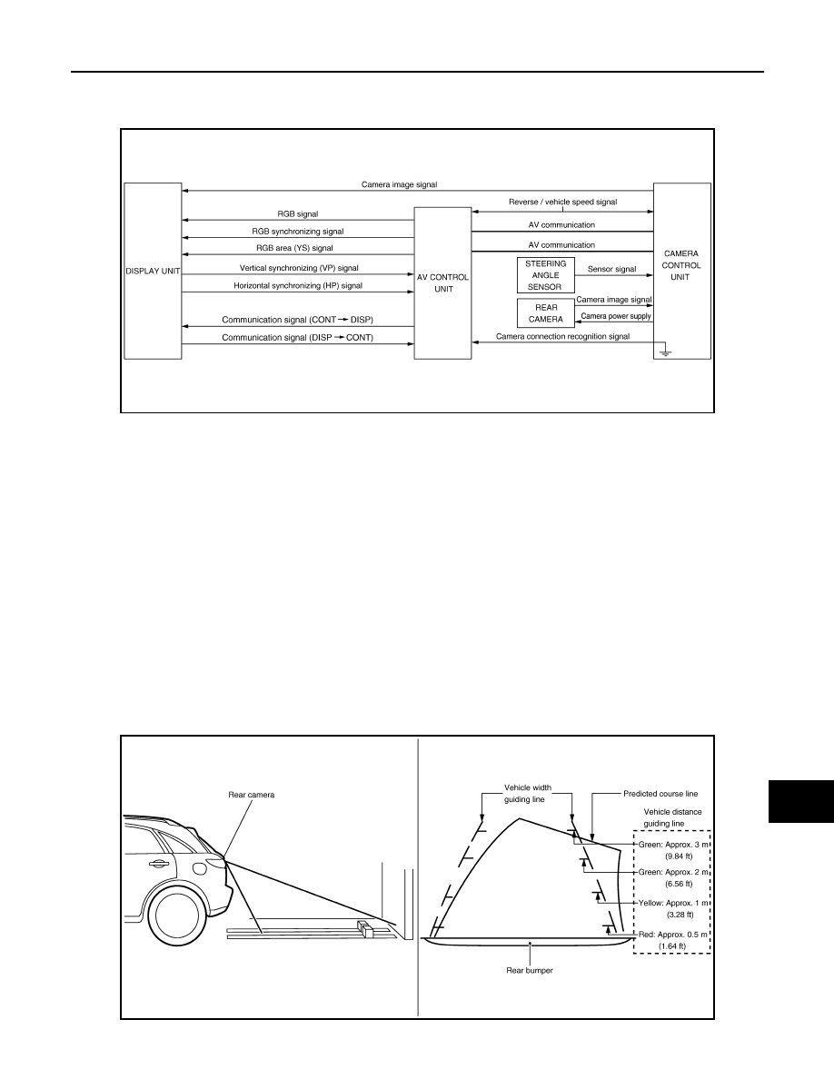
System Diagram
INFOID:0000000003160615
System Description
INFOID:0000000003515973
CAMERA IMAGE OPERATION PRINCIPLE
• Power is supplied to rear view camera from camera control unit and the rear view camera outputs the cam-
era image to the camera control unit when selector lever is set to reverse position and the reverse signal on
camera control unit is input.
• Camera control unit superimposes the guiding line and predicted course line to the image from rear view
camera and outputs to display unit. In this case, the reverse signal is also input to AV control unit. Therefore,
AV control unit recognizes the selector lever as in the reverse position. And then AV control unit switches the
image displayed by the communication signal between AV control unit and display unit with the camera
image.
• Camera control unit controls the direction and distance of the predicted course line according to the sensor
signal from steering angle sensor.
• AV control unit determines whether rear view camera is equipped or not, based on the presence of camera
connection recognition signal. It switches to rear view monitor image at the time of reverse signal input when
it is equipped.
• Warning message under the rear view monitor display is described by AV control unit.
Rear view monitor guiding line
JSNIA0704GB
JSNIA0707GB
AV-464
< FUNCTION DIAGNOSIS >
[BOSE AUDIO WITH NAVIGATION]
REAR VIEW MONITOR SYSTEM
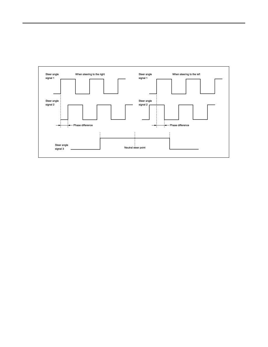
PREDICTED COURSE LINE OPERATION PRINCIPLE
Detection of steering rotation direction
Camera control unit detects the rotation direction of steering according to the phase difference of two pairs of
pulse signals (sensor signal 1 and sensor signal 2) input from steering angle sensor.
Detection of steering neutral position
The sensor signal 3 input from steering angle sensor is generated at 1 pulse per 1 steering wheel rotation.
Camera control unit detects the steering neutral position from this pulse.
Correction of steering neutral position
Camera control unit corrects the steering neutral position during driving according to the vehicle speed signal
and steering angle sensor signal.
JSNIA0708GB
Нет комментариевНе стесняйтесь поделиться с нами вашим ценным мнением.
Текст