Infiniti EX35. Manual — part 171
AV
REAR VIEW MONITOR SYSTEM
AV-465
< FUNCTION DIAGNOSIS >
[BOSE AUDIO WITH NAVIGATION]
C
D
E
F
G
H
I
J
K
L
M
B
A
O
P
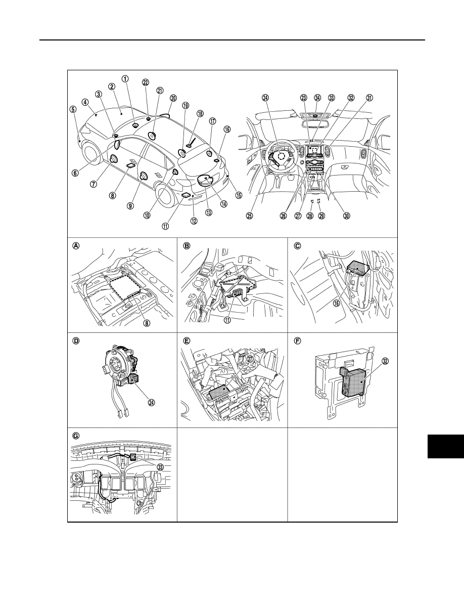
Component Parts Location
INFOID:0000000003579818
1.
Center speaker
2.
Corner sensor front RH
3.
Front squawker LH
4.
Front camera
5.
Corner sensor front LH
6.
Side camera LH
JPNIA0911ZZ

AV-466
< FUNCTION DIAGNOSIS >
[BOSE AUDIO WITH NAVIGATION]
REAR VIEW MONITOR SYSTEM
Component Description
INFOID:0000000003515974
7.
Front door speaker LH
8.
• Around view monitor control unit
(with around view monitor)
• Camera control unit (with rear view
monitor)
9.
Rear door speaker LH
10. Rear squawker LH
11. BOSE amp.
12. Corner sensor rear LH
13. Woofer
14. • Rear camera (with around view
monitor)
• Rear view camera (with rear view
monitor)
15. Corner sensor rear RH
16. Buzzer
17. Rear squawker RH
18. Antenna base (antenna amp and sat-
ellite antenna)
19. Rear door speaker RH
20. Side camera RH
21. Front door speaker RH
22. Front squawker RH
23. Display unit
24. Steering angle sensor
25. Steering switch
26. Preset switch
27. Sonar control unit (with around view
monitor)
28. iPod connector
29. Auxiliary input jacks
30. AV control unit
31. Multifunction switch
32. iPod adapter
33. GPS antenna
34. Microphone
A.
Under front seat (LH side)
B.
Luggage floor (LH side)
C.
Luggage side RH
D.
Spiral cable part
E.
Cluster lid C removed condition
F.
Rear view of the display unit
G.
Instrument panel rear side
Part name
Description
AV CONTROL UNIT
• Image on display is transmitted to rear view monitor image with serial commu-
nication between AV control unit and display unit.
• Warning displayed on the rear view monitor image is illustrated.
• AV control unit recognizes the presence of camera system with camera con-
nection recognition signal.
DISPLAY UNIT
• Camera image signal is transmitted from camera control unit, and RGB signal
for warning display is transmitted from AV control unit.
• Rear view monitor image is changed by communication from AV control unit.
CAMERA CONTROL UNIT
• Camera image signal is input from rear view camera. Camera image signal is
output to display.
• Power (camera ON signal) is transmitted to rear view camera.
• Superimpose the guiding line and predicted course line to the camera image
that outputs to display unit.
• Input the sensor signal from steering angle sensor, and then control the pre-
dicted course line.
• Camera control unit is connected via AV communication.
REAR VIEW CAMERA
• The image of vehicle rear view is transmitted to camera control unit.
• It receives power (camera ON signal) from camera control unit and operates.
STEERING ANGLE SENSOR
Steering signal necessary for predicted course line control is transmitted to cam-
era control unit.
AV
AROUND VIEW MONITOR SYSTEM
AV-467
< FUNCTION DIAGNOSIS >
[BOSE AUDIO WITH NAVIGATION]
C
D
E
F
G
H
I
J
K
L
M
B
A
O
P
AROUND VIEW MONITOR SYSTEM
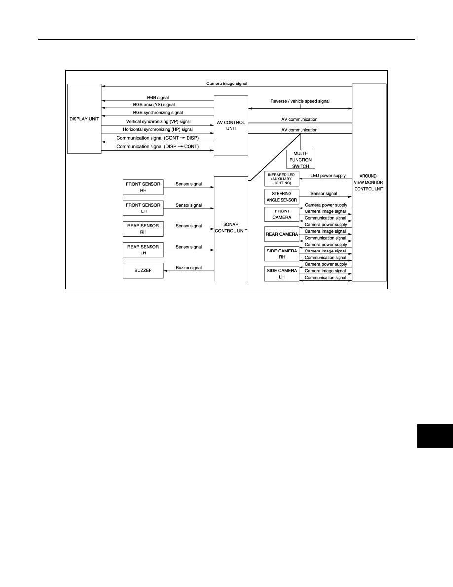
System Diagram
INFOID:0000000003160619
System Description
INFOID:0000000003160620
• This system is equipped with wide-angle high-resolution cameras on the front and rear of the vehicle and on
both right and left door mirrors. The images from front view, rear view, front-side view (RH side), and birds-
eye view that shows the view from the top of the vehicle are displayed to monitor the vehicle surroundings.
• Around view monitor control unit cuts out and expands the image received from each camera to create each
view.
• The sonar indicator is displayed on display (superimposed on the camera image) in combination with the
camera assistance sonar system to warm of the approach of an obstacle.
• In front view and rear view, the vehicle width, distance lines and predicted course lines are superimposed
and displayed. In front-side view, the vehicle distance guiding line and vehicle width guiding line are dis-
played.
• The Birds-Eye view converts the images from 4 cameras into the overhead view and displays the status of
the vehicle on display. The vehicle icon and sonar indicator that are displayed on the Birds-Eye view display
are rendered by around view monitor control unit.
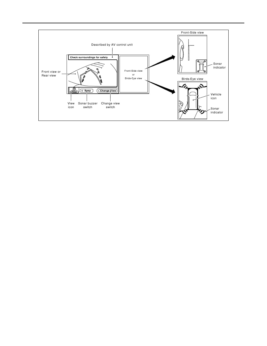
AROUND VIEW MONITOR SCREEN
• Around view monitor combines and displays the travel direction view and “Birds-Eye view”, “Front-Side
view”, and then it displays the sonar indicator on the “Birds-Eye view”, “Front-Side view”.
• AV control unit renders the “Change View”, “BEEP” switch, view icon, warning message on display.
JSNIA0705GB
AV-468
< FUNCTION DIAGNOSIS >
[BOSE AUDIO WITH NAVIGATION]
AROUND VIEW MONITOR SYSTEM
Screen constitution
OPERATION DESCRIPTION
• Around view monitor operates by pressing the “CAMERA” switch of multifunction switch and shifting the
selector switch to the reverse position.
• When the selector lever is in any position other than the reverse position, the screen is switched to the
around view monitor by pressing the “CAMERA” switch.
• The screen is switched to the around view monitor by shifting the selector lever to the reverse position.
• In the around view monitor, Birds-Eye view and Front-side view can be switched by pressing the “CAMERA”
switch or the touch switch of display.
• The “Front-Side and Front screen” are displayed as a priority when turning “Default to Front-Side View” ON.
• The around view monitor is cancelled 3 minutes after pressing the “CAMERA” switch, and then the screen
returns to the screen before displaying the around view monitor when selector lever is in a position other
than the “R” position.
• ON/OFF setting of sonar indicator display on the Front-Side view screen can be performed.
• In the Birds-Eye view, the invisible area is displayed on the image to specify the boundary of the 4 cameras.
The invisible area is displayed in yellow in the Birds-Eye view after turning the ignition switch ON.
• The sonar (both of buzzer and sound) operates only when the camera screen is displayed.
JSNIA0769GB
Нет комментариевНе стесняйтесь поделиться с нами вашим ценным мнением.
Текст